


16
CRYSTALVIEW PRO FIBER
INSTALLATION AND OPERATIONS MANUAL
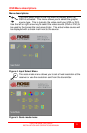
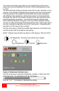
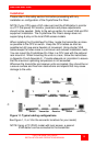
Refer to Figure 11 for the set-up for your system application.
A. 1- Connect the appropriate CPU cable to the keyboard, video
monitor and mouse ports on the CPU and to the
corresponding ports on the transmitter.
2- Connect the transmitter to the receiver with cable defined
for your system (CAT-5 or Fiber optic)
3- Connect the KVM stations keyboard, video monitor, and
mouse cables to the corresponding connectors on the
receiver unit.
B. 1- Connect the appropriate CPU cable to the keyboard, video
monitor and mouse ports on the CPU and to the appropriate
CPU connector on the switch.
2- Connect the appropriate KVM cable from the KVM port on the
switch to the corresponding connectors on the transmitter.
3- Connect the transmitter to the receiver with cable defined
for your system (CAT-5 or Fiber optic)
4- Connect the KVM stations keyboard, video monitor, and
mouse cables to the corresponding connector on the
receiver unit.
C. 1- Connect the appropriate CPU cable to the keyboard, video
monitor and mouse ports on the CPU and to the appropriate
CPU connector on the switch.
2- Connect the appropriate KVM cable from the KVM port on the
switch to the corresponding connectors on the transmitter.
3- Connect the transmitter to the receiver with cable defined
for your system (CAT-5 or Fiber optic).
4- Connect the appropriate CPU cable from the CPU port on the
switch to the corresponding connectors on the receiver
5-Connect the KVM stations keyboard, monitor, and mouse
cables to the corresponding connector on the receiver unit.
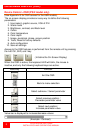
Transmitter to Receiver cabling
Cable type
Maximum distance
CAT-5
330’ / 100m
62.5µm MultiMode
600’ / 200m
50µm MultiMode
1,300’ / 400m
9µm SingleMode
33,000’ (6.25 miles) / 10km
Table 2. Transmitter to receiver cabling