


Page 10
ASSEMBLY
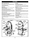
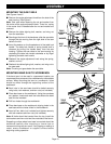
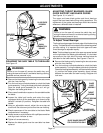
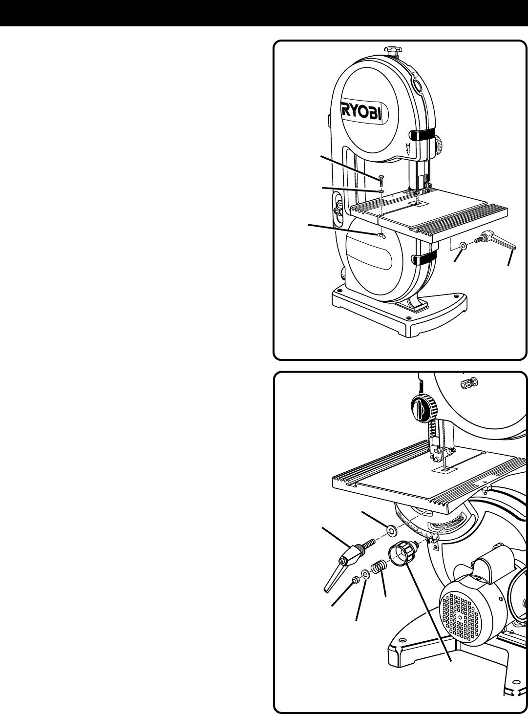
MOUNTING THE SAW TABLE
See Figures 4 and 5.
■ Remove the angle adjustment knob from the side of the
saw housing.
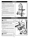
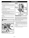
See Figure 5.
Note: Take care when removing the nut and washer from
the center of the angle adjustment knob. There is a spring
in the center that is released after the nut and washer are
removed.
■ Remove the table aligning bolt, washer, and wing nut
from the saw table.
■ Standing at the front of the band saw, slide the saw table
through the slot moving from the right side of the saw
table to the left.
■ Insert the washer on the threaded end of the table lock
handle. The table lock handle is spring loaded and is
released by pulling the handle away from the saw
housing. Tighten the saw table to the saw housing by
ratcheting the table lock handle clockwise or by finger
tightening the table lock handle.
■ Reattach the angle adjustment knob using the spring,
washer, and nut.
■ Reattach the table aligning bolt, washer, and wing nut to
the saw table.
Note: The wing nut goes below the saw table.
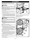
MOUNTING BAND SAW TO WORKBENCH
If the band saw is to be used in a permanent location, we
recommend that you secure it to a workbench or other stable
surface. When mounting the saw to a workbench, holes
should be drilled through the supporting surface of the
workbench.
■ Each hole in the saw base should be bolted securely
using bolts, lock washers, and hex nuts (not included).
■ Place band saw on the workbench. Using the saw base
as a pattern, locate and mark the holes where the band
saw is to be mounted.
■ Drill four holes through the workbench.
■ Place band saw on the workbench aligning holes in the
saw base with the holes drilled in the workbench.
■ Insert all four bolts (not included) and tighten securely
with lock washers and hex nuts (not included).
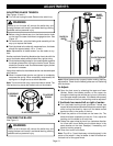
Note: All bolts should be inserted from the top. Install the
lock washers and hex nuts from the underside of the bench.
Supporting surface where band saw is mounted should be
examined carefully after mounting to insure that no
movement during use can result. If any tipping or walking is
noted, secure workbench or support surface before
beginning cutting operation.
TABLE
LOCK
HANDLE
Fig. 4
O
N
R
E
M
O
V
E
T
O
L
O
C
K
O
9”
BAND
SAW
WING
NUT
WASHER
TABLE
ALIGNING
BOLT
WASHER
Fig. 5
0
15
4
5
30
ANGLE
ADJUSTMENT
KNOB
TABLE
LOCK
HANDLE
WASHER
SPRING
WASHER
NUT