


Page 14
ADJUSTMENTS
■ Remove the blade guard by loosening the two set screws
with the 4 mm hex key.
■ Turn the lock lever counterclockwise to unlock the blade
guide assembly. Turning the blade guide knob clockwise,
raise the blade guide assembly as far as it will go.
Retighten the blade guide knob.
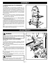
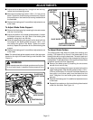
■ Place a small combination square on the saw table beside
the blade.
■ Loosen the table lock handle and rotate the angle
adjustment knob to tilt the saw table up or down to align
table 90° to blade (0° position). Retighten the table lock
handle.
■ Using an adjustable wrench, adjust the zero stop set
screw until the set screw just touches the saw housing.
■ Check squareness of the saw table to the blade. Make
readjustments if necessary.
■ Loosen screw on scale indicator with a phillips screwdriver
and align scale indicator to zero.
■ Tighten all screws securely.
■ Replace the blade guard once the saw table has been
squared.
WARNING:
Failure to turn the saw off, remove the switch key, and
unplug the saw could result in accidental starting causing
possible serious personal injury.
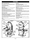
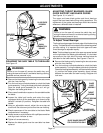
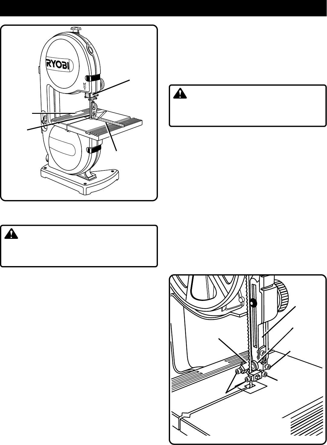
SQUARING THE SAW TABLE TO THE BLADE
See Figure 12.
WARNING:
Failure to turn the saw off, remove the switch key, and
unplug the saw could result in accidental starting causing
possible serious personal injury.
■ Remove the blade guard by loosening the two set screws
with the 4 mm hex key.
■ Turn the lock lever counterclockwise to unlock the blade
guide assembly. Turning the blade guide knob (clockwise
raises the blade guide assembly, counterclockwise lowers
it), position the blade guide assembly about halfway
between the saw table and saw housing. Retighten the
lock lever.
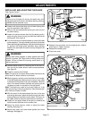
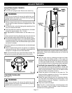
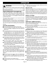
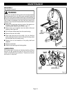
ADJUSTING THRUST BEARINGS, BLADE
GUIDE SUPPORT, AND BLADE GUIDES
See Figures 13, 14, and 15.
The upper and lower blade guides and thrust bearings
support the band saw blade during cutting operations. The
adjustment of the guides and bearings should be checked
whenever a different blade is installed.
To Adjust Thrust Bearings:
The thrust bearings support the back edge of the blade during
cutting. The blade should not contact the thrust bearings when
you stop cutting. It is important that both upper and lower
thrust bearings be adjusted equally.
Note: The thrust bearing screw is the upper cap screw located
on the right side of the blade guide assembly. It is the lower
cap screw on the right side of the saw housing below the
saw table for the lower bearing.
See Figures 13 and 14.
BLADE
GUIDE
ASSEMBLY
BLADE GUIDE
SUPPORT SCREW
BLADE GUIDE
SCREWS
UPPER BLADE
GUIDE SUPPORT
BLADE GUARD REMOVED
FOR CLARIFICATION ONLY
THRUST
BEARING
THRUST BEARING
SCREW
Fig. 13
BLADE GUIDE
ASSEMBLY
ZERO STOP
SET SCREW
Fig. 12
3
M
A
X
I
M
U
M
C
U
T
T
I
N
G
C
A
P
A
C
I
T
Y
O
N
R
E
M
O
V
E
T
O
L
O
C
K
O
9”
B
A
N
D
SA
W
SMALL
COMBINATION
SQUARE
SAW
BLADE