


Page 12
ADJUSTMENTS
WARNING:
Failure to turn the saw off, remove the switch key, and
unplug the saw could result in accidental starting causing
possible serious personal injury.
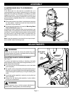
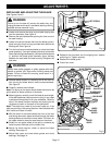
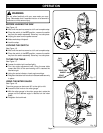
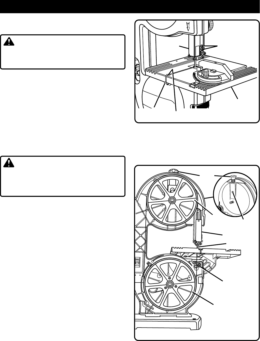
INSTALLING AND ADJUSTING THE BLADE
See Figures 8 and 9.
■ Loosen and remove the wing nut and table aligning bolt
from the saw table.
See Figure 8.
■ Remove the saw table before opening the front cover of
the saw housing.
■ Loosen the two set screws that hold the blade guard in
place using the 4 mm hex key provided then remove the
blade guard.
See Figure 8.
■ Turn the lock lever counterclockwise to unlock the blade
guide assembly. Turning the blade guide knob (clockwise
raises the blade guide assembly; counterclockwise lowers
it), position the blade guide assembly about halfway
between the saw table and saw housing. Retighten the
lock lever
.
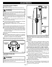
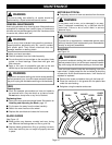
WARNING:
Always wear safety goggles or safety glasses with side
shields to protect your eyes while uncoiling band saw
blades. Failure to heed this warning could result in a
serious eye injury.
■ Release blade tension by loosening the 8 mm hex nut
then turning the blade tension knob counterclockwise
.
See Figure 9.
■ Carefully remove the old blade.
Note: The spring on the upper wheel allows the wheel to be
pulled down for easier removal of the blade.
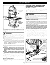
■ Wearing gloves, carefully uncoil the blade at arms length.
If the new blade was oiled to prevent rusting, it may need
to be wiped to keep the oil from your workpiece. Carefully
wipe in the same direction the teeth are pointing so the
rag does not catch on the teeth of the saw blade.
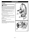
Note: The blade may need to be turned inside out if the
teeth are pointing in the wrong direction. Hold the blade with
both hands and rotate it inward.
■ With the teeth of the blade toward the front of the saw
and facing downward, place the blade through the lower
blade guides and around the lower wheel. Pull down on
the upper wheel to place the saw blade on the wheel.
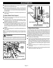
■ Slowly turn the upper wheel to the right or clockwise by
hand to center the blade on the rubber tires.
■ Adjust the blade tension; check or adjust the blade
tracking. See page 13.
■ Adjust both upper and lower blade guides and thrust
bearings. See page 14.
■ Reattach the saw table and the aligning bolt, washer,
and wing nut. Tighten securely.
■ Reattach the blade guard.
■ Close front cover.
Fig. 9
LOWER
WHEEL
BLADE TENSION
KNOB
LOWER
BLADE
GUIDES
BLADE GUIDE
ASSEMBLY
SAW BLADE
UPPER
WHEEL
O
N
O
F
F
SAW
TABLE
ON
M
O
V
E
L
O
C
K
O
30
45
60
7
5
90
7
5
6
0
45
3
0
Fig. 8
WING
NUT
BLADE
GUARD
TABLE ALIGNING
BOLT
SET SCREWS
8mm HEX NUT