


Page 10
ASSEMBLY
WARNING:
Do not connect to power supply until assembly is
complete. Failure to comply could result in accidental
starting and possible serious personal injury.
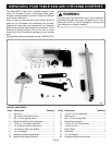
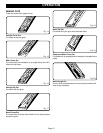
TOOLS NEEDED
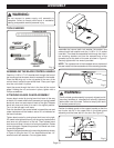
Fig. 3
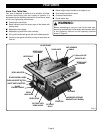
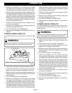
ASSEMBLING THE BLADE CONTROL HANDLE
Feed the 1/4-20 x 2-7/16” shoulder bolt through the front of
the handle so that the screw head is recessed in the handle.
Place the M6 wing nut in the nut pocket in the rear of the
control wheel, behind the pre-drilled hole. Place your finger
over the nut to hold it in place.
Insert the screw through the hole in the front of the control
wheel. Holding the nut and screw in place, tighten with a
Phillips screwdriver.
ATTACHING BLADE GUARD ASSEMBLY
Loosen bevel control by turning bevel lock lever all the way
to the left. If it needs to be further loosened, pull spring-loaded
bevel lock lever out and rotate it back to the right. Release
bevel lock lever and allow it to seat in its original position.
Turn it to the left again until loose.
Push the handle on the control wheel in toward the saw and
rotate clockwise until the blade is set to 90° as indicated on
the bevel indicator.
Tighten bevel control by turning bevel lock lever to the right.
If it needs to be tightened more, pull the spring-loaded bevel
lock lever out and rotate it to the left. Then release bevel
lock lever and allow it to return to its original position. Rotate
to the right again. Repeat this process until bevel lock lever
is securely tightened.
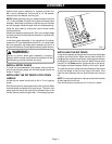
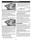
Fasten the support bracket to the mounting bracket as shown
in Figure 4 using the two 1/2" hex head bolts and two 1/4"
external tooth lock washers. Do not tighten bolts.
FRAMING SQUARE
ADJUSTABLE
WRENCH
#2 PHILLIPS
SCREWDRIVER
COMBINATION
SQUARE
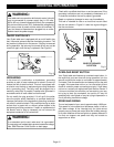
Assemble the internal tooth lock washer, flat washer, and
external tooth lock washer onto the 1/4-20 x 2-1/4” socket
head bolt. Then feed the assembled bolt through the hole in
the mounting bracket and into the exposed end of the
threaded rod at the back of the saw as show in Figure 5.
Securely tighten with hex wrench provided.
NOTE: The exposed end of the threaded rod on the back of
the saw inserts into the recessed end of the mounting bracket.
Fig. 4
WARNING:
Confirm blade guard assembly is properly aligned and all
mounting hardware is attached and securely tightened
before each use of the saw. Failure to comply can result
in serious personal injury.
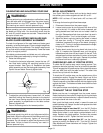
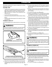
Position the blade guard on the support bracket so that the
top circular tab fits in the upper hole in the blade guard
assembly and the lower tab is in the slot.
See Figure 6.
Fig. 5
Fig. 6
WASHER