


Page 13
3. To adjust the vertical alignment, loosen the 2-1/4” socket
head bolt holding the mounting bracket to the back of
the saw. Use a framing square to make sure the blade
guard assembly is perpendicular to the table surface.
Securely tighten bolt.
4. Return the blade guard to the lowered position.
WARNING:
If the blade guard/riving knife is out of alignment with the
saw blade, adjust the alignment of the blade guard/riving
knife assembly and securely tighten all mounting
hardware. Do not attempt to adjust the alignment of the
saw blade. Failure to heed this warning can result in
serious personal injury.
ADJUSTMENTS
CALIBRATING AND ADJUSTING YOUR SAW
WARNING:
Before performing any adjustments or calibrations, make
sure the table saw is unplugged from the power supply
and the switch is in the "OFF" position. Failure to heed
this warning can result in serious personal injury.
Before operating your saw, check for proper alignment of
the blade and riving knife. You should also check that the
90° and 45° positive stops are accurate. These should be
done prior to each use.
CHECKING/ADJUSTING SAW BLADE AND
BLADE GUARD ASSEMBLY ALIGNMENT
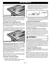
To check the alignment of the saw blade and blade guard
assembly, raise the blade guard. Place a straight edge flush
against the face of the saw blade. The straight edge should
line up flush with the blade guard assembly. Lower the blade
guard to its original position.
If the blade guard assembly and blade are not in alignment,
adjust the blade guard assembly by doing the following:
1. Raise the blade guard.
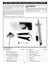
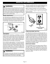
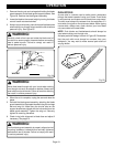
2. To adjust the horizontal alignment, loosen the two 1/2"
hex head bolts holding the mounting bracket to the
support bracket.
See Figure 10.
Reposition the blade
guard assembly so that the blade guard assembly lines
up with the saw blade. Securely tighten bolts.
BEVEL ADJUSTMENTS
Your Ryobi Table Saw has a rack and pinion bevel control
that allows you to make angled cuts from 90° to 45°.
NOTE: A 90° cut has a 0° bevel and a 45° cut has a 45°
bevel.
To change the bevel angle follow these steps.
1. Disconnect the saw from the power supply.
2. Loosen bevel control by turning bevel lock lever all the
way to the left. If it needs to be further loosened, pull
spring-loaded bevel lock lever out and rotate it back to
the right. Release bevel lock lever and allow it to seat in
its original position. Turn it to the left again until loose.
3. Adjust the bevel angle by pushing the wheel in toward
the saw then turning it. Turning the wheel counter-
clockwise increases the angle of the blade, bringing it
closer to 45°. Turning it clockwise decreases the angle,
bringing the blade closer to 90°.
4. Tighten bevel control by turning bevel lock lever to the
right. If it needs to be tightened more, pull the spring-
loaded bevel lock lever out and rotate it to the left. Then
release bevel lock lever and allow it to return to its original
position. Rotate to the right again. Repeat this process
until bevel lock lever is securely tightened.
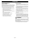
CHECKING 90° AND 45° POSITIVE STOPS
To check the 90° positive stop, use a framing square. First,
make sure the bevel indicator is as far to the left as possible.
This will engage the 90° positive stop. Next, place the square
with one side flush with the table surface. The other side
should line up flush with the blade.
To check the 45° positive stop, use the angled corner of the
combination square. Engage the bevel control and tilt the
blade all the way to the right to engage the 45° positive stop.
Place the square on the table surface with the angled corner
against the blade. The blade and table should both be flush
with the square.
If the positive stops need adjusting, proceed as follows.
TO ADJUST THE 90° POSITIVE STOP
Make sure the saw is unplugged from the power source.
Raise the blade to the maximum height by turning the blade
control wheel counterclockwise. Loosen the bevel control by
turning the bevel lock lever to the left.
Next, push the blade control wheel in toward the saw and
rotate clockwise until it stops. Use the framing square to check
the position of the blade.
If the blade angle is less than 90°, turn the 90° Positive
Stop Adjustment Screw counterclockwise one turn. Push the
blade control wheel in and rotate counterclockwise until it
stops. Recheck the blade position. Continue this process
until the blade is at 90°. Tighten the bevel control lever.
If the blade angle is greater than 90°, use the framing
square to position the blade to 90°. Turn the 90° Positive
Stop Adjustment Screw clockwise until it stops. Tighten the
bevel control lever.
Fig. 10