


Page 14
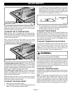
4. For non-through cuts, use a ruler or other graduated
straight-edge to measure from the table surface to the
tip of the uppermost tooth on the blade.
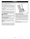
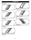
TO ADJUST THE RIP FENCE
To reposition the rip fence, lift the lock down handle to the
Up position (parallel to the fence). Use the indicator on the
fence to slide the fence to the desired position. Make sure
the front bar on the rip fence is flush against the front rail.
Then move the lock down handle to the Down position
(perpendicular to the fence).
TO ADJUST TENSION ON THE RIP FENCE
To avoid risk of kickback and to ensure accuracy, the rip
fence must be securely attached to the front rail and rear
edge. If there is lateral play in the fence, tighten the
adjustment nut at the back of the fence. If the rip fence lock
down lever is too tight, loosen the adjustment nut.
WARNING:
The rip fence must be positioned parallel to the miter
gauge channel to prevent risk of kickback.
To ensure proper alignment, use a framing square to measure
the distance from the front end of the rip fence to either of
the miter gauge channels. Then measure from the rear end
of the fence to the same miter gauge channel. If the two
measurements are not the same, reposition the rear end of
the fence and measure again.
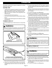
TO ADJUST THE MITER GAUGE
To adjust the miter gauge, simply loosen the lock knob and
rotate the miter gauge to the desired position. Then tighten
the lock knob.
NOTE: There are two miter gauge channels, one on either
side of the blade. When making a 90° cross-cut, you can
use either miter gauge channel. When making a beveled
cross cut (the blade tilted in relation to the table) the miter
gauge should be located in the slot on the right so that the
blade is tilted away from the miter gauge and your hands.
Reset the Bevel Indicator to 90° by loosening the screw
holding the indicator. Line up the red line on the indicator
with the 0° mark on the bevel scale.
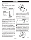
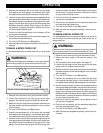
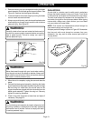
TO ADJUST THE 45° POSITIVE STOP
Make sure the saw is unplugged from the power source.
Raise the blade to the maximum height by turning the blade
control wheel counterclockwise. Turn the bevel lock lever to
the left to loosen the bevel.
Next, push the blade control wheel in and rotate
counterclockwise until it stops. Check the blade position using
the angled corner of a combination square or triangle.
ADJUSTMENTS
Fig. 11
90° POSITIVE STOP
ADJUSTMENT SCREW
If the blade angle is greater than 45°, turn the 45° Positive
Stop Adjustment Screw counterclockwise 1 turn and rotate
the bevel control wheel counterclockwise until it stops.
Recheck the blade position. Continue this process until the
blade is at 45°. Tighten the bevel control lever.
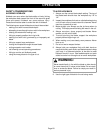
If the blade angle is less than 45°, use the combination
square or triangle to position the blade at 45°. Turn the 45°
Positive Stop Adjustment Screw clockwise until it stops.
Tighten the bevel control lever.
Reset the Bevel Indicator to 45° by loosening the screw
holding the indicator. Line up the red line on the indicator
with the 45° mark on the bevel scale.
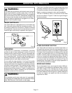
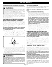
TO ADJUST THE BLADE HEIGHT
1. Disconnect saw from power supply.
2. Turn blade control wheel. Turning it clockwise lowers the
blade. Turning it counterclockwise raises it.
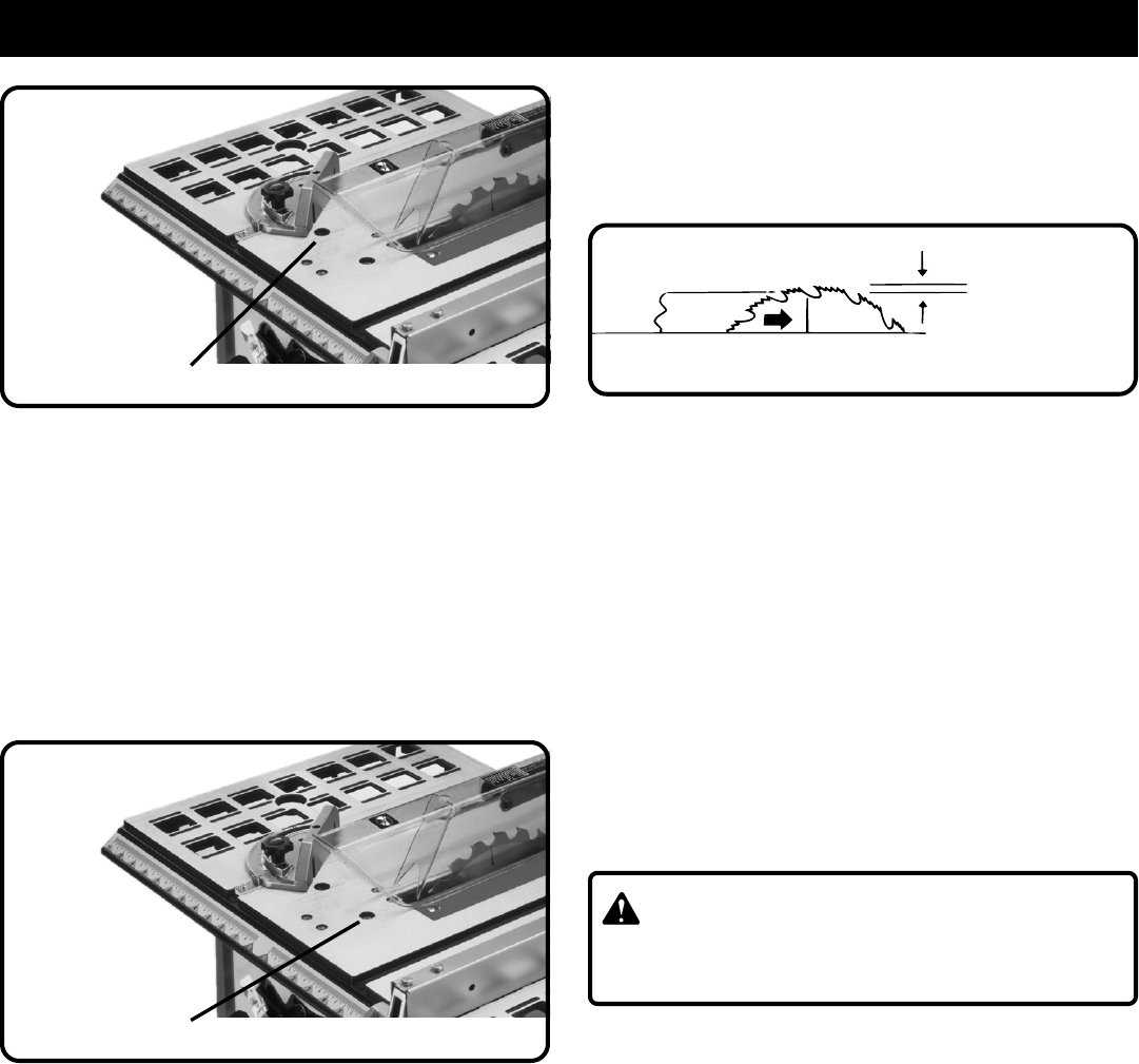
Fig. 13
Fig. 12
45° POSITIVE STOP
ADJUSTMENT SCREW
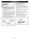
APPROXIMATELY
1/8”
3. For through-cuts, place the workpiece to be cut flush
against the blade. Set the blade so that the tips of the
uppermost tooth are about an 1/8" (3 mm) higher than
the workpiece and the valley between the teeth (gullet)
is lower than the workpiece as in Figure 13.