


Page 11
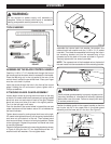
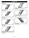
Attach blade guard assembly to support bracket with
M6 x 19 mm carriage bolt. Secure with a 1/4" flat washer,
external tooth lock washer and wing nut.
NOTE: Before tightening wing nut, make sure there is at least
1/8" (3 mm) between the end of the table and blade guard
assembly. Also check to make sure that the two circular tabs
are still engaged inside the upper hole and slotted opening.
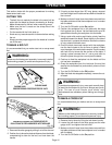
Raise the saw blade by turning the control wheel handle
counterclockwise.
Raise the transparent blade guard, then use a straight edge
to make sure that the blade guard assembly is aligned with
the saw blade.
If the blade guard assembly is not aligned with the blade,
loosen the 1/2" hex head bolts and/or the 2-1/4” socket head
bolt and reposition the blade guard assembly so that it is
aligned with the blade. Once aligned, securely tighten all bolts.
WARNING:
Failure to confirm blade guard assembly is properly
aligned with the blade could cause the workpiece to jam
while sawing, causing kickback and injury.
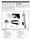
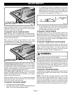
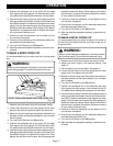
INSTALL MITER GAUGE
To install the pre-assembled miter gauge, simply slide the
long end of the miter gauge into the miter gauge channel as
shown in Figure 7.
INSTALLING THE RIP FENCE LOCK DOWN
HANDLE
Locate the lock down handle and an M4 x 15 mm tapping
screw.
Slide the handle over the exposed end of the rip fence. Make
sure the handle is inserted as far as it can go. The hole in the
metal rip fence should line up with the recessed hole in the
handle. Secure handle using the M4 x 15 mm tapping screw.
ASSEMBLY
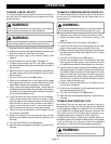
INSTALLING THE RIP FENCE
The rip fence attaches to the rear and front rails by two flanges
on either end of the fence. When the lock down handle is in
the Up position (parallel to the fence), the flanges are relaxed,
allowing you to reposition the rip fence. When the lock down
handle is in the Down position (perpendicular to the fence),
the flanges are drawn together and the rail is held in place.
To install the rip fence, place the end furthest from the handle
so that the flange is over the rear edge of the table. Then
lower the end closest to the lock down handle over the front
rail.
NOTE: For accurate alignment, make sure that the front block
is flush against the front rail.
Push the lock down handle down to fix the rail in place.
Fig. 7