12
ADJUSTMENTS
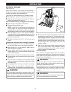
■ Lock plunge lock lever to position cutter at "zero"
depth of cut.
■ Adjust hex nuts until they come in contact with stop
flange. This will provide a position stop at “zero”
depth of cut.
■ Make sure the hex nuts are securely tightened against
each other.
■ Rotate depth stop to desired position, loosen lock
knob and adjust stop bar until it touches depth stop.
■ Slide zero-reset indicator up or down the scale on
stop bar until red line on zero-reset indicator aligns
with a desired reference point. For example, align
red line with 1 in. (25.4 mm) mark on the scale.
■ Lift stop bar to obtain desired depth of cut.
For
example, if setting 1/8 in. (3.2 mm) depth of cut, the
zero-reset indicator will move 1/8 in. (3.2 mm) from
the 1 in. (25.4 mm) reference point.
■ Tighten lock knob securely.
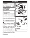
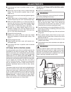
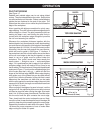
■ Position your router so that the cutter can extend
below the subbase for desired depth setting.
See
Figure 7.
■ Unlock plunge lock lever.
■ Grasp handles and lower router until stop bar con-
tacts depth stop.
■ Lock plunge lock lever to position cutter at desired
depth of cut.
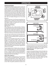
OPTIONAL DEPTH CONTROL KNOB
An optional depth control knob is available and may be
purchased for use with your plunge router. We recom-
mend its use when your routing needs require precise
depth of cut adjustments and when router is mounted
upside down on a UL listed router table. NOTE: The
weight of the router plus the awkward position it is in when
mounted to a router table make it very difficult to set depth
of cut simply by turning the hex nut with a
15/16 in. (23.8 mm) wrench. Therefore, we recommend
that you purchase and use a depth control knob for
situations mentioned above as well as other similar
situations.
The optional depth control knob is spring loaded against
hex nut to prevent router motor from accidently sepa-
rating from router base. If depth control knob is turned
too far up depth adjustment rod, the spring will cause
depth control knob to pop off before hex nut. Do not
remove hex nut. It should remain on depth adjust-
ment rod at all times. This is especially important when
using router upside down on a router table.
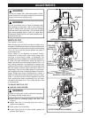
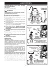
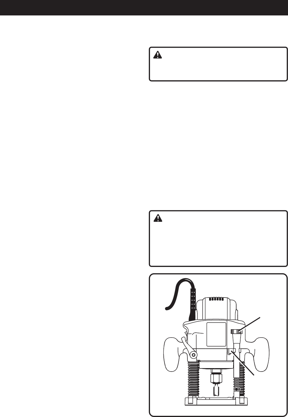
TO INSTALL OPTIONAL DEPTH CONTROL KNOB
See Figure 8.
■ UNPLUG YOUR ROUTER.
WARNING:
Failure to unplug your router could result in acciden-
tal starting casuing serious injury.
■ Remove upper hex nut from depth adjustment rod.
NOTE: This is the only time you should remove the
hex nut from the router. Also, if you remove the
optional depth control knob for any reason, you must
reinsall the hex nut before reusing the router.
■ Turn remaining hex nut counterclockwise until 1/4 in.
(6.35 mm) of thread is remaining at the top of the
depth adjustment rod.
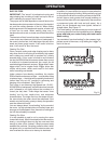
■ Place compression spring on top of hex nut as shown
in Figure 8.
■ Place optional depth control knob on top of com-
pression spring and align tabs on depth control knob
with flats on hex nut.
■ Compress spring by carefully pushing down on top
of depth control knob.
■ Thread depth control knob clockwise onto depth ad-
justment rod.
WARNING:
Relacing optional depth control knob without com-
pression spring could result in depth control knob
and hex nut vibrating off depth adjustment rod. This
situation could cause motor to separate from router
base, resulting in possible serious injury.
Fig. 8
OPTIONAL DEPTH
CONTROL KNOB
STOP
FLANGE


