


10
ASSEMBLY
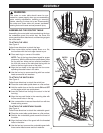
Fig. 5
Fig. 7
Fig. 6
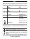
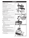
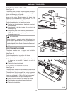
TO ATTACH THE FENCE
See Figure 5.
Follow these directions to attach the fence.
Q Place the router table right side up with the back
edge closest to you.
Q Position the fence on the table with the four black
knobs facing you.
Q Align the two holes on the bottom of the fence with
the two channels on the router table.
Q Secure the fence to the table with the two fence lock
knobs and carriage bolts.
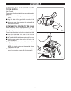
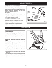
TO ATTACH THE CUTTER GUARD ASSEMBLY/
VACUUM ATTACHMENT
See Figure 6.
Follow these directions to attach the cutter guard
assembly/vacuum attachment.
Q Place the router table right side up with the back
edge closest to you.
Q Screw the guard post securely into one of the
threaded holes on the top of the fence.
NOTE: When the fence is close to the cutter, place
the guard post in the off-center threaded hole to
provide protection from the cutter and allow for proper
suction for the vacuum.
Q Loosen the clear plastic ring by turning the black
knob counterclockwise.
Q Slide the ring over the guard post.
Q Center the cutter guard over the throat of the router
table.
Q Tighten the cutter guard by turning the black knob
clockwise.
NOTE: While routing, you can insert a standard
shop vacuum into the top of the clear plastic ring to
keep dust down to a minimum.
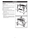
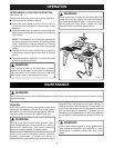
TO ATTACH THE MITER GAUGE
See Figure 7.
Follow these directions to attach the miter gauge.
Q Place the router table right side up with the front
edge closest to you.
Q Place the miter gauge bar in the track near the front
of the table with the pointer on the right.
Q Position the miter gauge onto the miter gauge bar
placing the miter gauge under the pointer and align-
ing the hole in the miter gauge over the small post in
the miter gauge bar.
Q Screw the miter gauge knob into the threaded hole
in the miter gauge bar.