


9
ASSEMBLY
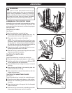
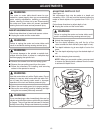
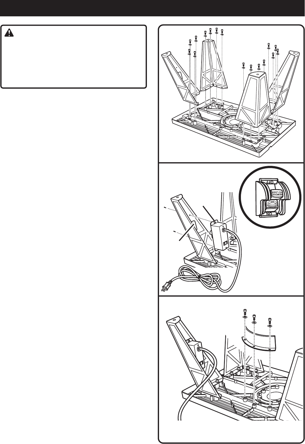
Fig. 2
WARNING:
The router or router table should never be con-
nected to a power supply when you are assembling
parts, making adjustments, installing or removing
cutters, cleaning, or when not in use. Disconnecting
the router and router table will prevent accidental
starting that could cause serious personal injury.
ASSEMBLING THE ROUTER TABLE
Assembling the router table involves attaching the legs,
the undertable guard, the switch box, the fence, the
cutter guard/vacuum attachment, and the miter gauge to
the router table.
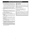
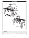
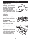
TO ATTACH THE LEGS
See Figure 2.
Follow these directions to attach the legs.
Q Place router table surface upside down on a flat,
level surface with the front edge closest to you.
Q Place each leg in a corner of the table.
NOTE: Two of the legs have been keyed for proper
placement. With the table surface upside down, place
the leg with four holes and two punched notches in
the front left corner of the table and the leg with six
holes in the front right corner of the table.
Q Align the four holes in the legs with the four corre-
sponding threaded holes in the table.
Q Use the hex key to secure each leg with four socket
head screws and lock washers.
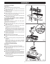
TO ATTACH THE SWITCH BOX
See Figure 3.
Follow these directions to attach the switch box.
Q Place the router table upside down on a flat surface.
Q Hold the switch box so that the words ON and OFF
on the toggle switch are upside down.
Q Insert the switch box through the cutout in the left
front leg.
Q Align the two small holes in the mounting tabs with
the two small holes in the leg.
Q Use a screwdriver to secure the switch box with two
thread cutting screws.
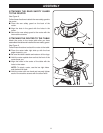
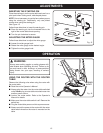
TO ATTACH THE UNDERTABLE GUARD
See Figure 4.
Follow these directions to attach the undertable guard.
Q Place the router table upside down on a flat surface.
Q Position the undertable guard around the throat of
the table.
Q Align the three holes of the guard with the threaded
holes in the table.
Q Use the hex key to secure the undertable guard with
three socket head screws and lock washers.
Fig. 4
Fig. 3
SWITCH
BOX
CUTOUT