


14
ADJUSTMENTS
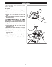
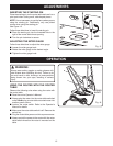
INSERTING THROAT PLATES
See Figure 12.
The throat plate provides a stable surface around the
cutter and prevents objects from falling through the
throat and damaging the spindle.
The proper size throat plate depends on the size and
shape of the cutter. When inserted, the throat plate
opening should be within approximately 1/4 in.
(6.4 mm) of the outermost edge of the cutter.
Follow these directions to insert throat plates.
Q Position the throat plate over the throat opening in
the router table.
Q Align the tab in the throat plate with the slot in the
throat opening.
Q Snap throat plate down and into place as shown.
NOTE: To remove throat plate, pull gently until the
throat plate snaps out.
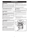
WARNING:
Never attempt to operate router table without the
throat plate in place. Failure to do so could result in
the workpiece jamming or objects falling into the
rotating spindle, which could cause serious personal
injury.
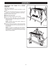
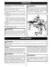
POSITIONING THE FENCE
The fence enables you to support and guide the
workpiece.
See Figure 13.
Follow these directions to position the fence.
Q Loosen the fence lock knobs.
Q Position the fence the proper distance from the cut-
ter based on the amount of material you plan to
remove.
Q Tighten the fence lock knobs.
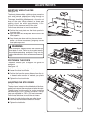
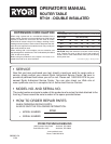
ADJUSTING THE STEP RISERS
See Figure 14.
The step risers, located on the outfeed side of the fence,
enable you to support the workpiece as it exits the cutter.
The step risers provide support for routing operations
that remove up to 1/8 in. (3.2 mm) of material. The step
risers are adjustable in 1/32 in. (0.8 mm) increments.
Follow these directions to adjust the step risers.
Q Loosen the knob bolts on the rear of the fence.
Q Push the riser forward and toward the throat.
Q Tighten the knob bolts.
Fig. 12
Fig. 13
Fig. 14
4
3
2
in./po./pulg.
1
2
1
2