


▪ 11 ▪
DO NOT attempt to start a vehicle without the battery properly installed. Damage may result
to the vehicle’s electrical system.
7.5 OVERLOAD PROTECTION
The charger uses an output circuit breaker and a thermal breaker to prevent overheating and
damage to the charger and the vehicle. If after repeated starting attempts, the charger does not
indicate any output on its meter, it may be because one of the two breakers has opened. If the
output breaker opens due to excessive current, a popping noise will be heard. It will automatically
reset itself in a few minutes. If the thermal breaker opens, it will automatically reset itself in about
15 to 30 minutes. Output over-voltage will show as 19.9 and the FAIL LED will light.
7.6 Display and Accuracy
Voltage
• Open circuit voltage between 12.0–13.0 is displayed to 0.1 V and is accurate to +/- 0.1 V at
DC levels.
•
Open circuit voltage below 12.0 or above 13.0 is displayed to 0.1 V and is accurate to +/- 2%.
• Charging voltage is displayed to 0.1 V and is accurate to +/- 2%.
Current
• Below 10 A, current is displayed to 0.1 A and is accurate to +/- 0.3 A.
• At 10 A or above, current is displayed to 0.1 A and is accurate to +/- 5%
Amp Hours
• Amp Hours are measured in whole units and represent the charge sent to the battery
NOTE: This is NOT a measurement of actual battery amp hours, but a running display
of how many amp hours the battery is currently accumulating.
Charge Time
• In Battery Test Mode, the timer displays a countdown timer from 15 minutes to zero.
• In Battery Charge Mode, the timer displays a total elapsed time.
8. BASIC OPERATION
8.1 BATTERY CHARGE ACCEPTANCE TEST
NOTE: This is NOT the same as a conductance test, for which the battery
analyzers mentioned in paragraph 7.4 are used.
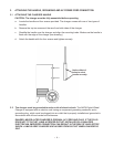
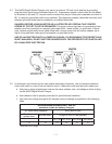
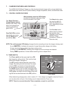
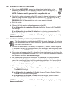
a. With charger unplugged, set both dials to test mode (point to white battery illustration
boxes on each dial).
b. Hook the cables to battery, red to positive (+) post and black to negative (-) post. (If polarity
is reversed, attaching the second clamp will cause a spark. Reverse the clamps.) The
battery voltage will appear on the front panel display, and the PASS/FAIL LEDs will blink
alternatively until the 15 minute test time elapses.