


assembly
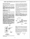
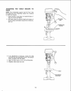
WARNING: FOR YOUR OWN SAFETY, NEVER CON-
NECT PLUG TO POWER SOURCE OUTLET UNTIL
ALL ASSEMBLY STEPS ARE COMPLETED.
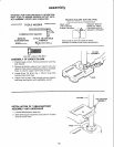
TOOLS NEEDED
'[' _.... I f' '1" I'
.I, • ], I,'I. I • , ,
MEDIUM
SCREWDRIVER
COMBINATION SQUARE
8-INCH ADJUSTABLE
WRENCH
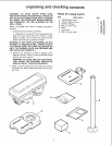
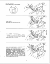
DRAW LIGHT
LINE ON BOARD
ALONG THIS EDGE _. ?',_
f,÷_ •
SHOULD BE NO GAP OR OVERLAP WHEN
SQUARE IS FLIPPED OVER IN DOTTED POSITION
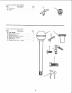
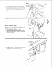
8mm DIA. x 20mm LONG BOLT
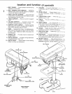
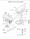
ASSEMBLY OF BASE/COLUMN
1. Position base on floor. Remove protective covering
and discard.
2. Remove protective sleeve from column tube and
discard. Place column assembly on base, and align
holes in column support with holes in base.
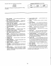
3. Locate three (3) 8ram Dia. x 20ram long bolts
among loose parts bag.
4. Install a bolt in each hole through column support
and base and tighten with adjustable wrench.
FRAMING SQUARE MUST BE TRUE.
Check its accuracy as illustrated below.
STRAIGHT EDGE OF
BOARD 3/4" THICK--
THIS EDGE MUST BE
PERFECTLY STRAIGHT
COLUMN
ASSEMBLY
BASE
COLUMN
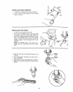
TABLE/SUPPOR
ASSEMBLY
INSTALLATION OF TABLE/SUPPORT
ASSEMBLY AND HARDWARE
1. Locate table/support assembly
2, Slide table/support assembly onto column. Position
directly above base.
BASE
10