


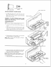
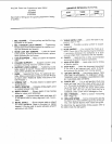
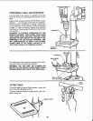

ThisDrillPresshas3 speedsaslistedbelow:
620RPM
!300RPM
31OORPM
Seeinsideofbeltguardforspecificplacementofbelts
onpulleys.
SPINDLE SPEEDS BN R.P.M.
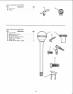
1, BELT GUARD .... Covers pulleys and belt during
operation of drill press.
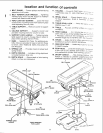
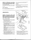
2. BELT TENSION LOCK HANDLE ... Tightening
handle locks motor bracket support to maintain cor-
rect belt distance and tension.
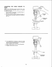
3. HEAD LOCK :SET SCREWS... Locks the head
to the column. ALWAYS have them locked in place
while operating the drill press.
4, TABLE SUPPORT ... Rides on column to support
table.
5. COLUMN SUPPORT . . . Supports column and
provides mounting holes for column to base.
6. SUPPORT LOCK HANDLE... Tightening locks
table support to column. Always have it locked in
place while operating the Drill Press.
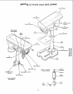
7. BASE... Supports Drill Press. For additional sta-
bility, holes are provided in base to bolt Drill Press
to bench (See "Additional Safety Instructions for
Drill Presses.")
8. SPRING CAP... Provides means to adjust quill
spring tension.
9. DEPTH POINTER... Indicates drilling depth and
is located between stop nuts.
10. DEPTH SCALE . .. Shows depth of hole being
drilled in inches and millimeters.
11. COLUMN... Connects head, table, and base on
a one-piece tube for easy alignment and move-
ment.
t2. BEVEL SCALE .... Shows degree table is tilted
for bevel operations. Scale is mounted on table
support. It if to be used for quick reference where
accuracy _snot critical.
t3. TABLE BEVEL LOCK... Locks the table in any
position from O_-45 °.
14. TABLE... Provides working surface to suoport
workpiece.
15. FEED HANDLE... For moving the chuck up or
down. One or two of the handles may be removed
if necessary whenever the workpiece is of such
unusual shape that it interferes with the handles,
16. CHUCK... Holds drill bit or other recommended
accessory to perform desired operations.
17. FEED STOP ROD... Holds stop nuts for drilling
to specific depths.
t8. STOP NUTS... Limits the downward movement
of the quill at any desired point within its t_avel,
and prevents the pointer from moving upward.
19. "ON-OFF SWITCH... Has locking feature. THIS
FEATURE IS INTENDED TO PREVENT UNAU-
THORIZED AND POSSIBLE HAZARDOUS USE
BY CHILDREN AND OTHERS.
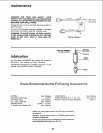
20. CHUCK KEY . . . It is a self-ejecting chuck key
which will "pop" out of the chuck when you let go
of it, This action is designed to help prevent throw-
ing of the chuck key from the chuck when power
is turned "ON". Do not use any other key as a
substitute, order a new one if damaged or lost.
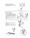
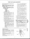
21. BELT TENSION... Refer to section "Tensioning
Belt" (Page 13).
22. DRILLING SPEED... Can be changed by placing
the belt in any of the STEPS (grooves) in the pul-
leys. See Spindle Speed chart inside belt guard.
To determine the approximate drilling speed, refer to
the table inside the belt guard.
16