


-13-
N(.(,Fne\ijDXelXcD]^%J`eZ\)&'/
J<KLG
Although the main components of the E:AB8AJ
W1715
are assembled at the factory, some assembly is required.
The following series of instructions are the recommended
sequence best suited for the machine assembly.
KffcjE\\[\[ Hkp
Safety Glasses .....................................1 Per Person
Wrench 12mm ...................................................1
Wrench 14mm ...................................................1
Additional Person (for lifting) .................................1
Sawhorses ........................................................2
Pliers ..............................................................1
Phillips Screwdriver #2 .........................................1
Straightedge 12" Minimum .....................................1
KfXjj\dYc\k_\YXe[jXn#[fk_\j\jk\gj1
(% Unfold the two stand leg assemblies. They are
hinged on the edges for easy setup.
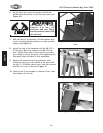
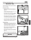
)% Use the M6-1 x 12 hex bolts, M6-1 hex nuts, and
6mm flat washers to install the corner support
braces in the bottom corners of the leg assemblies
(=`^li\ /).
*% On one of the leg assemblies, attach the wheel
mounting bracket along with the corner support
braces to the outside bottom edge, as shown in
=`^li\/.
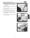
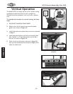
+% Slide the axle through the holes in the wheel
mounting bracket.
,% Slide the wheels onto the axle on the outside of the
mounting brackets, and secure them with the cotter
pins, as shown in =`^li\0.
D8B< JLI< k_Xk pfli
dXZ_`e\ `j legcl^^\[
[li`e^ Xcc Xjj\dYcp
gifZ\[li\j @] k_`j
nXie`e^ `j `^efi\[#
j\i`flj g\ijfeXc `ealip
dXpfZZli%
8jj\dYcp
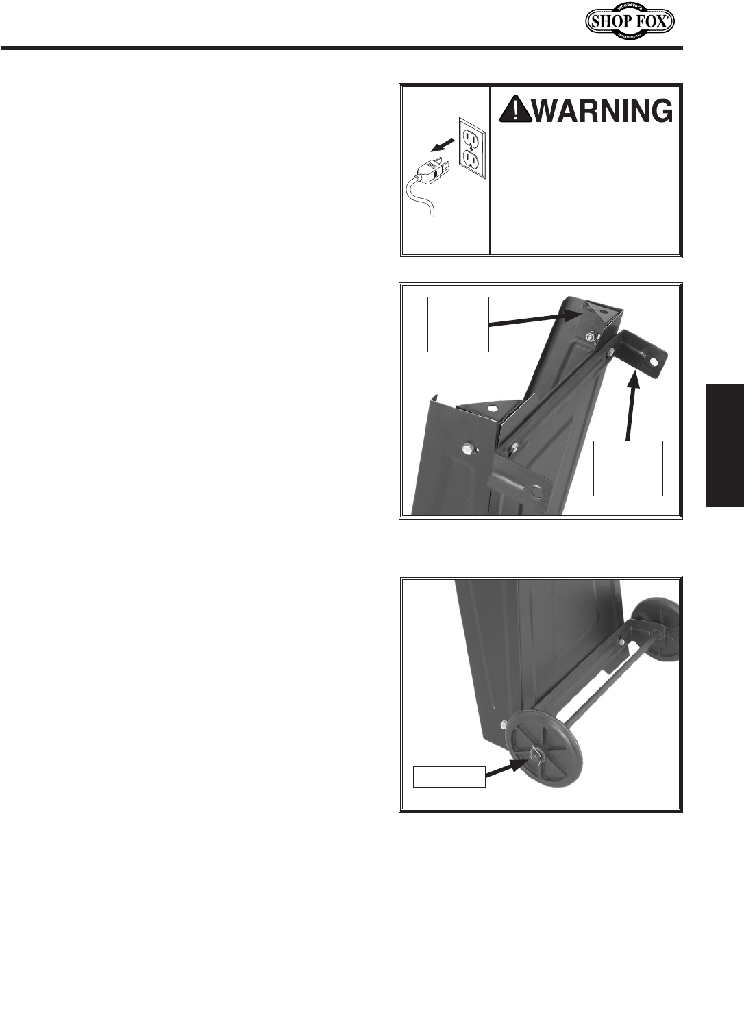
=`^li\/% Corner support brace and wheel
mounting bracket.
Corner
Support
Brace
Wheel
Mounting
Bracket
=`^li\0% Wheel installed with cotter pin.
Cotter Pin