


-11-
W1755 6" Parallelogram Jointer
SETUP
NOTICE
When ordering replacement parts, refer
to the parts list and diagram in the back
of the manual.
The following is a description of the items shipped with
the SHOP FOX
®
Model W1755.
Note:
If you can't find an item on this list, check the
mounting location on the machine or examine the pack
-
aging materials carefully
. Occasionally we pre-install cer-
tain components for safer shipping.
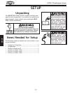
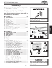
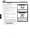
Box 1: (Figure
7) Qty
A. Jointer Assembly ..........................................1
B. Carriage .....................................................1
C. Fence ........................................................1
D. Extension Table ............................................1
E. Push Blocks .................................................2
F. Cutterhead Guard .........................................1
G. Hex Wrenches 2.5, 4, 5, 6, 8mm ................1 Each
H. Handle .......................................................1
I. Fence Tilt Lever ...........................................1
J. Open-end Wrench 8/10, 12/14mm .............. 1 Each
K. Knife Setting Jig (not shown) ............................1
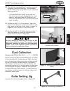
Box 2: (Figure
8) Qty
L. Stand Assembly w/Motor .................................1
M. Pedestal Switch ............................................1
N. Wheel Assembly ...........................................1
O. Belt Guard ..................................................1
P. Dust Port ....................................................1
Q. V-Belt ........................................................1
Assembly Fasteners Qty
• Hex Bolt M8-1.25 x 50 (Wheel/Stand) .................
1
• Flat Washer 8mm (Wheel/Stand) .......................
1
• Hex Bolts M10-1.5 x 55 (Wheel/Stand) ................
2
• Flat Washers 10mm (Wheel/Stand) ....................
2
• Hex Nuts M10-1.5 (Wheel/Stand) .......................
2
• Cap Screws M8-1.25 x 25 (Jointer/Stand) .............
4
• Lock Washers 8mm (Jointer/Stand) ....................
4
• Flange Bolts M6-1 x 12 (Belt Guard) ...................
2
• Hex Nuts M6-1 (Belt Guard) .............................
2
• Flat Washers 6mm (Belt Guard) .........................
2
• Cap Screws M6-1 x 20 (Extension Table) ..............
2
• Cap Screw M10-1.5 x 30 (Carriage) .....................
1
• Cap Screw M10-1.5 x 50 (Carriage) .....................
1
• Flat Washers 10mm (Carriage) ..........................
2
• Cap Screws M8-1.25 x 30 (Fence) .......................
2
• Cap Screws M10-1.5 x 25 (Pedestal) ...................
2
• Lock Washers 10mm (Pedestal) .........................
2
• Flat Washers 10mm (Pedestal) ..........................
2
• Phillips Screws M5-.8 x 16 (Dust Port) .................
4
• Flat Washers 5mm (Dust Port) ..........................
4
Inventory
Figure 8. Box 2 inventory.
L
M
N
O
Q
P
Figure 7. Box 1 inventory.
A
H
B
D
E
F
I
G
C
J
Power must not be connected to
machine during setup!