


-16-
W1755 6" Parallelogram Jointer
SETUP
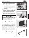
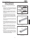
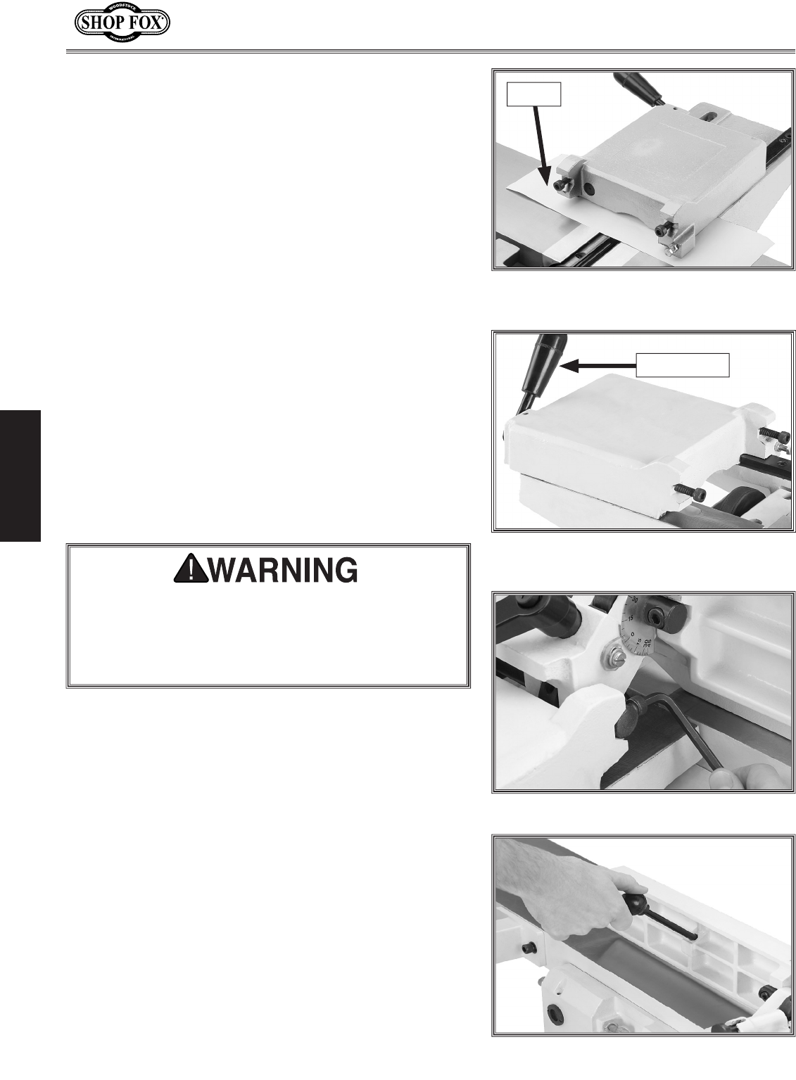
Figure 19. Fence carriage mounted on the
back of the jointer.
Lock Handle
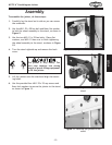
21. Attach the carriage to the back of the jointer with
the M10-1.5 x 30 cap screw on the infeed side, the
M10-1.5 x 50 cap screw on the outfeed side, and two
10mm flat washers. Leave the cap screws loose for
now.
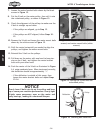
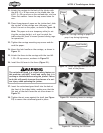
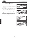
22. Place three pieces of paper on the jointer bed, slide
the top half of the carriage over the paper, and
allow it to rest on the paper, as shown in
Figure 18.
Note: The paper acts as a temporary shim for set
-
ting the carriage height, so it won't scratch the
table when the fence is moved forward during regu
-
lar operations.
23. Tighten the carriage mounting cap screws and dis-
card the paper.
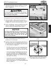
24. Mount the lock handle on the carriage, as shown in
Figure 19.
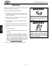
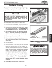
25. Attach the fence to the carriage with the two M8-
1.25 x 30 cap screws, as shown in
Figure 20.
26. Install the tilt lever in the fence (Figure 21).
Figure 20. Attaching fence to carriage.
Figure 21. Installing the tilt lever.
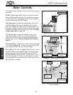
The cutterhead guard is a critical safety feature on
this machine—you MUST install and verify that it is
working as intended before using the jointer! Failure
to do this will greatly increase the chances of a seri
-
ous injury when operating the jointer.
Figure 18. Carriage resting on paper to
prop it up during tightening.
Paper
27. Insert the cutterhead guard shaft into the hole at
the front of the infeed table, making sure that the
flat part of the shaft faces the set screw shown in
Figure 22.
28. Tighten the set screw against the shaft (see Figure
22) to secure the cutterhead guard in place.