


-9-
Model W1821 (For Machines Mfg. Since 3/10)
SETUP
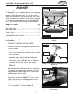
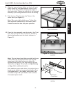
Figure 11. T-slot bars installed for one of
four orientations.
T-Slot Bars
8. When the saw and router tables are level with each
other, rotate the foot pad assembly so that it sits
firmly on the floor without changing the height of
the router table. Tighten the jam nut of the foot pad
assembly up to the leg bottom to secure the setting.
9. Slide the two T-slot bars into the T-slots of the
router table (see Figure 11).
Note: The router table double-cross T-slots offer
four different orientations for the router fence—
choose the one that best suits your operation.
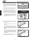
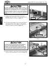
10. Place the fence assembly over the studs of the T-slot
bars, then secure the fence in place by threading
the knurled handles onto the studs, as shown in
Figure 12.
Figure 12. Fence knurled handles
installed.
Knurled Handles
Shims
Outfeed
Fence Board
Fence
Figure 13. Shim installation for full edge
routing.
Note: The two fence board shims provided with your
router table can be placed between the outfeed
fence board (left) and the fence to offset the
outfeed fence board for full edge routing (see the
illustration in Figure 13 and refer to Edge Routing
on Page 15 for additional details).
With additional shop-made shims, the outfeed fence
board can be offset up to approximately 4mm from
the infeed board. If you require more offset, you
can obtain longer M6-1 flat head screws to secure
the outfeed fence board.