


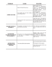
PERFORATING ONLY
If what you want is simply to make perforations in the material, you must place a new complete set
of dies and make the following adjustments:
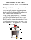
With the machine disconnected from the power source:
- Empty both the deposits and railings of any grommets and washers,
- Move the grommet railing to the left and secure it with a small puncher to the front raceway
bracket part nº 272 ,
- Next place the new complete set of dies and adjust the machine’s pressure.
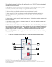
- In the control panel “IMO V3” the washer detector switch must be set to the “0” position.
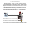
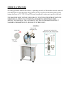
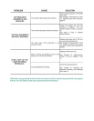
PLACEMENT LASER LIGHT (OPTIONAL ACCESSORIES)
- Your machine has an optional laser light that emits a red laser beam that can help with the
placement of the grommet and washer.
- The machine includes a switch for this device, in the “IMO V3”. For connecting the switch
see Electric installation.
Note: Although the light power of this laser is very small. DO NOT SHINE THIS LIGHT
DIRECTLY IN ANYONE’S EYES SINCE IT COULD BE HARMFUL. KEEP IT AWAY FROM
CHILDREN.
- For small grommets and washers, the machine may come with a little air pipe attached to the
washer raceway, which blows the washer down onto their right position, by means of an air
compressor.
- For placing grommets and washers in materials such as: canvas, sailcloth, etc, a small metallic tray
may be attached to the machine, in order to be used as a base for the material.
- If you wish to know the amount of grommets and washers that you set each day, you can use a
grommet and washer meter.
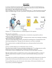
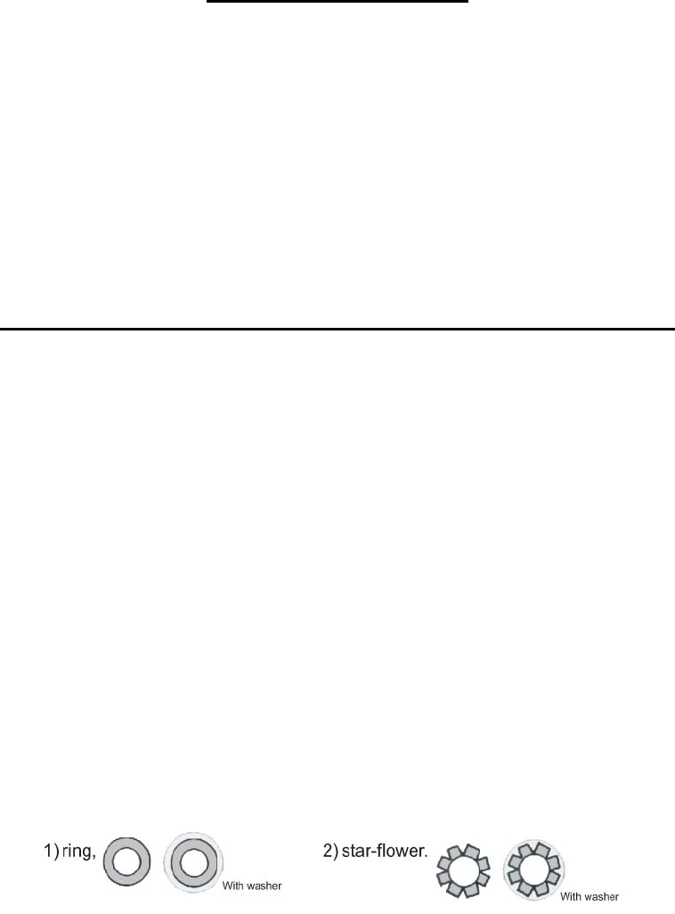
- The back side of the grommet may have two shapes after having been placed in the material: 1)
ring shaped grommeting, 2) star-flower shaped grommeting, depending on the kind of bottom die
that you use:
Ask for the flower-shaped or ring-shaped bottom die nº 219 according to the kind of grommeting
that you wish to obtain.
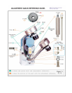
Due to differences in the tension of different supply systems, the top-set spindle stop-position nº 218
may not be correct, and the spindle stops at a point lower than normal. If you change the position of
the detector screw nº 171 by screwing it into another hole (generally the one next to it) of the
flywheel nº 274, we will be able to stop the top set spindle nº 218 in another position. The correct
position is as high as possible.