


10.
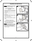
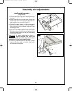
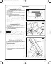
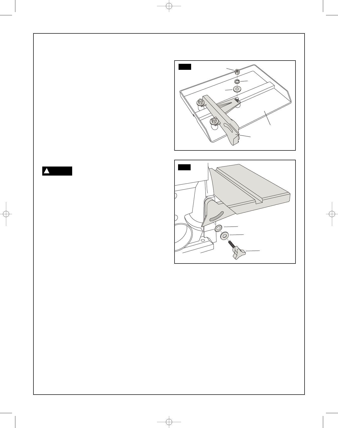
Installing table assembly
(Fig. 5 & 6)
1. Position table support (1) against table (2) and align
the holes.
2. Using three M6 hex nuts (3), three spring lock
w
ashers
(
4)
,
and three flat washers
(
5)
,
fasten the
table support to the work table (Figure 5).
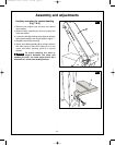
3. Position the table support in the corresponding
holes on the side of the base, as shown in figure 6.
Ensure that the 9.5 mm diameter index pin aligns
with the upper hole.
4. Place a 6.5 mm washer (6) and a tooth lock washer
(7) on the end of the table lock knob (8) and insert
through the table support slot and into the threaded
hole of base (Figure 6).
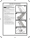
To avoid trapping the work or
fingers between the table and
sanding surface, the table edge should be a
maximum of 1-2 mm from sanding surface.
5. Loosen the three hex head nuts at bottom of table
support and adjust table as required. Adjust table
as necessary and retighten.
Assembly and adjustments
WARNING
!
FIG. 5
FIG. 6
1
7
6
8
3
5
4
2
SM 2610957110 05-08 6/5/08 7:36 AM Page 10