


Instruction Manual
Model 4105 Gas Sensor Module (12/02)
Page: 7
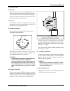
6.4a.Combustibles
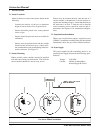
1. Verify the voltage across A to R equals 2 volt. If
not, adjust volts potentiometer R11
2. Verify the voltage from GND (TB2) to VOUT
equals 0.4 volts. If not adjust BAL potentiom-
eter (R2)
3. Verify that the voltage at VOUT is equal to the
voltage desired.
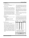
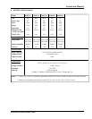
• The VOUT test point on the I/O PCB has a range
of 0.4-2 volts for 0-100% of the measurement
range. Therefore, 0%=0.4 volts, 25%=0.8,
50%=1.2 volts, 75%=1.6 volts, 100%=2 volts.
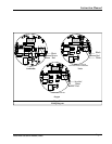
• Selecting the jumper at JP1 assigns one of four
different sensitivity ranges to the module. The
JP1 positions are labeled 1, 2, 3 & 4. JP1 jumper
set the coarse up scale SPAN values by affect-
ing the gain of the analog circuit. JP1 is set
correctly if an application of 50% of full scale
reads between 1.0 & 1.4 volts on VOUT. Fine-
tuning of these setting is done later by adjust-
ing the 4105-02 magnetic control.
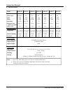
JP1 gain values are as follows:
JP1 with jumper in position 1 = GAIN = 51
JP1 with jumper in position 2 = GAIN = 26
JP1 with jumper in position 3 = GAIN = 12.5
JP1 with jumper in position 4 = GAIN = 7
JP1 with no jumper = GAIN = 1
• More than one jumper may be installed to allow
additional gain value. Multiple jumper are addi-
tive in relation of the gain value. For example, if
a gain of 20 is needed, jumper should be placed
in positions 3 and 4 to provide a gain of 20.
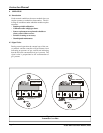
6.4b LEL Sensor Fault Supervision
The typical failure mode of catalytic bead sensors
is the reference or active beads open circuit. In
rare cases a short circuit may develop. The 4105-
02 is equipped with fault detection circuitry that
detects either condition. A FAULT is also signaled
if the output drifts below -10% of full scale. The
4105-02 signals a FAULT condition exists by over-
writing the LCD with a FLt message, flashing the
red LED on the front panel and clamping the 4-
20mA output at 0mA. These conditions remain until
the FAULT is corrected.
6.4c Electrochemical (Oxygen and Toxics)
Verify that the voltage VOUT is equal to the volt-
age as desired.
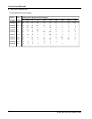
• The VOUT test point on the I/O PCB has a range
of 0.4-2 volts for 0-100% of the measurement
range.
• The 4105-XX has 4 fixed ranges of sensitivity,
which are selectable via JP1.
• The JP1 positions are labeled 1, 2, 3 & 4.
• JP1 jumper set the coarse up scale SPAN values
by affecting the gain of the analog circuit.
• JP1 is set correctly if a 50% of full-scale gas
read between 1.0 & 1.4 volts on VOUT.
• Fine-tuning of these settings is done later by
adjusting the 4105-XX via magnetic control.
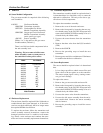
• Select the jumper at JP1 as required. JP1 gain
values are as follows:
JP1 with jumper in position 1 = GAIN = 5.5
JP1 with jumper in position 2 = GAIN = 4
JP1 with jumper in position 3 = GAIN = 2.3
JP1 with jumper in position 4 = GAIN = 1.5
JP1 with no jumper = GAIN = 1
• More than one jumper may be installed to allow
additional gain value. Multiple jumper are addi-
tive in relation of the gain value. For example, if
a gain of 6.5 is needed, jumper should be placed
in positions 2 and 3 to provide a gain of 6.3.
Note: Allow the new sensor to stabilize for a mini-
mum of 30 minutes and then calibrate using the
procedure in Section 5.
6.4d Missing Electromechanical Sensor Fault Supervision
Many electromechanical sensor housings allow for
easy replacement of defective sensors by making the
sensors 'plug in'. A problem is that if the sensor is
removed, many transmitters continure to display the
safe reading of 0 PPM. The 4105-XX is equipped with
fault detection circuitry that detects a missing sensor.
Within several minutes of removing an EC sensor, the
4105-XX will signal a FAULT condition. A FAULT is
also detected if the sensor output drifts below -10%
of full scale. the Model 4105-XX demonstrates a
FAULT condition exists by overwriting the LCD read-
ing with FLt, illuminating the red LED on the front
panel and by clamping the 4-20mA output at 0mA.
These conditions exist until the FAULT is corrected.