


Model 4105 Gas Sensor Module (12/02)
Page: 2
Instruction Manual
2. CAUTIONS WARNINGS &
RECOMMENDATIONS
2.1 INTRODUCTION
Although the sensor module is designed and con-
structed for installation and operation in industrial
applications including “hostile” environments, cau-
tion should be taken to insure that the installation is
in compliance with this instruction manual and that
certain procedures and conditions are avoided.
READ AND UNDERSTAND THIS INSTRUCTION
MANUAL BEFORE OPERATING OR SERVICING
THIS EQUIPMENT.
2.2 WIRING
Electro magnetic and radio frequency interference to
the analog communication between the sensor and
the controller may occur. The manufacturer recom-
mends that extra caution be taken where the installa-
tion is near any sources of these interferences:
Avoid running sensor cable close to high power
cables, radio transmission lines, or cables subject to
pulses of high current. Avoid running cables near
large electric motors or generators.
Use shielded cable in any location which may be ex-
pected to be electrically noisy or where cable is ex-
pected to be in close contact with AC wiring. The
shield should be connected to the controller com-
mon, one side only.
The wiring should be run in either a cable tray or
conduit as required by applicable code and area clas-
sification. Control wiring should not be installed in a
cable tray or conduit with higher voltage and AC cir-
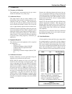
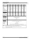
cuits. See Table 2.1 for recommended wire gauge.
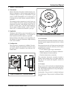
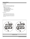
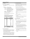
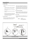
Wiring connections at the gas sensor module are as
follows:
Wire# Function Terminal
1 Power PWR
2 Signal SIG OUT
3 Ground GND
Connect an earth ground to the ground screw pro-
vided in the base of the gas sensor module enclo-
sure.
All splices must be via either a lug and terminal sys-
tem or soldered. Improperly spliced cable can result
in corrosion, resistance changes and system errors.
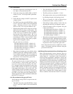
Wire Gauge Maximum Length
20 AWG 2,000 Ft.
18 AWG 3,000 Ft.
16 AWG 4,000 Ft.
14 AWG 6,500 Ft.
12 AWG 9,000 Ft.
Table 2.1
Recommended Wire/Cable Gauge
NOTE: Temperature rating of cable wire insulation
must be above 75
o
C (85
o
C or greater rated wiring is
recommended). If cable runs through higher tempera-
ture environments, it should be specified for that en-
vironment.
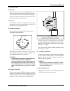
2.3 SENSOR MODULES - GENERAL
Sensors should be facing down. Avoid installing sen-
sor modules where they will be unnecessarily exposed
to wind, dust, water (esp. direct hose down), shock,
or vibration. Observe temperature range limitations.
Sensors may be adversely affected by prolonged ex-
posure to certain materials. Loss of sensitivity, or
corrosion, may be gradual if such materials are present
in low concentrations. These materials include: Ha-
lides (compounds containing chlorine, fluorine, bro-
mine, or iodine), silicones, acid vapors, caustic liq-
uids or vapors.
Sensor modules must not be painted. Paint may con-
tain compounds which will contaminate the sensor.
Paint will also cause clogging of the sintered metal
cup and will cause difficulties during attachment of
the calibration fitiing. The module should be tagged
“DO NOT PAINT”.
When sensors are replaced the thread on the sensor
housing must be lubricated with an antizieze com-
pound non-silicone based to avoid metal to metal
binding which will damage the housing threads.
2.4 PREVENTATIVE MAINTENANCE
DUST AND DIRT CONTROL: When calibration is
performed the controller and sensors should be
checked visually to determine if dust or dirt build up
needs to be removed. This cleaning should be done
with dry instruments such as compressed air, cloth
wipes or wisk broom.
WIRING OR CABLE CONDITIONS: Any wiring or
cables which are not in conduit should be checked
once a year for damage to insulation or corrosion
of splice or terminal points.