


Instruction Manual
Model 4105 Gas Sensor Module (12/02)
Page: 3
3. QUICK START
3.1 Overview
The gas sensor module has been supplied factory cali-
brated and ready for immediate installation and opera-
tion. An installer familiar with installation and opera-
tion of gas detection products can use this section to
begin immediate use of the monitor.
3.2 Wiring
Provide three conductor wiring from the power sup-
ply/control device to the sensor module location. See
section 2.2 for wiring specifications.
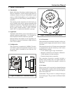
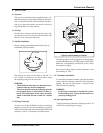
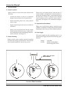
3.3 Module Installation
Remove spring on electromechanical sensor prior to
installation. See Figure below.
The module can either be installed on the end of a
3/4" conduit, or attached to a vertical surface using
the mounting flange on the enclosure.
WARNING:
- The installation must meet any hazardous envi-
ronment codes for electrical equipment.
- The sensor module enclosure mounting must be
far enough from any vertical surface to allow re-
moval and replacement of the sensor assembly
which is threaded into the second 3/4" conduit
hub.
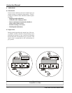
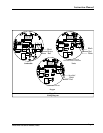
3.4 Wiring Connection
To gain access to the I/O PCB for wiring or mounting
purposes, loosen the two captive thumb screws in the
4105-XX front panel and remove the PANEL/CPU PCB
assembly as far as is allowed by the ribbon cable.
Terminal positions on the I/O printed circuit assembly
are labeled PWR (power), OUTSIG (signal), GND (TB2).
Make the corresponding connections to the control
device/power supply.
The sensor harness should remain connected to the
I/O assembly at “TB1”.
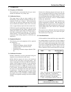
3.5 Transmitter Installation
To install the front panel assembly, align the two thumb
screws with their mating stand-offs and firmly hand
tighten. Be sure the front panel is centered in the
4105-XX housing opening.
WARNING:
- If the sensor transmitter is installed in a classi-
fied hazardous area, replace the threaded cover
prior to providing power.
3.6 Start-up & Operation
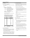
To begin operation of the sensor module provide 21-30
VDC from a regulated power supply.
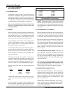
Figure 3.1
Typical Vertical Mounting on Conduit
FAULT
ZEROSPAN
Unity
MODEL 4105-05
HS PPM
2
GAS MONITOR
PPM