


Model 4105 Gas Sensor Module (12/02)
Page: 8
Instruction Manual
7. INSTALLATION
7.1 Sensor Locations
Select locations for each of the sensors based on the
following:
- Consider the density of the gas to determine
height of sensor above floor or ground level.
- Sensors should be placed close to the potential
source of gas.
- Sensors should be placed in areas accessible for
calibration.
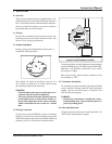
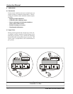
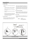
- Sensors must be pointed down and the conduit
should include an inverse trap to reduce mois-
ture (condensation) from accumulating in the elec-
tronics enclosure. See Figure 7.1.
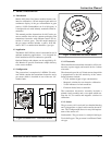
7.2 Sensor Mounting
Where possible sensor modules should be installed
with the sensor facing vertically down. The lid of the
sensor module should face out for easy access.
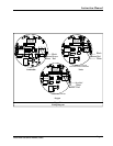
Sensors may be mounted directly onto the end of a
vertical conduit, or bracketed to a vertical surface us-
ing the two mounting flanges. Insure that the body of
the enclosure is at least 1" from the wall so that the
sensor assembly can be rotated for removal and re-
placement. See Figure 6.1 for installation configura-
tions.
7.3 Explosion Proof Installation
Where area classification requires explosion proof
(NEMA-7) installation a sealing fitting will be required
immediately above the gas sensor module enclosure.
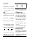
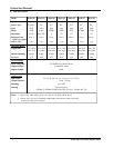
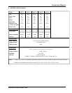
7.4 Power Supply
The power supplied by the controlling device or an
external power supply must meet the following speci-
fications:
Voltage: 21-30 VDC
Current: 180 mA (Combustibles)
40 mA (Oxygen & Toxics)
Figure 7.1
Gas Sensor Module Installation