


Instruction Manual
Model 4105 Gas Sensor Module (12/02)
Page: 5
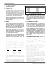
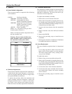
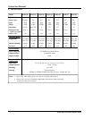
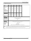
Model Gas Min. Flow Rate
(cc/min)
4105-02 CH
4
100
4105-03 O
2
100
4105-04 CO 150
4105-05 H
2
S 300
4105-06 Cl
2
300
4105-07 H
2
300
4105-10 SO
2
300
4105-12 NO
2
300
4105-21 HCl 300
4105-22 HCN
*
300
4105-25** NH
3
400
4105-26 HF 500
*Note: SO
2
may be used instead of HCN to
calibrate: 10ppm SO
2
= 16 ppm HCN
*Note: H
2
S may be used instead of HCl to
calibrate: 10 ppm H
2
S = 20 ppm HCl
** Note: Use permeation tube for 4105-25
5. CALIBRATION
5.1 Frequency of Calibration
The manufacturer recommends that the gas sensor
module be calibrated every ninety days.
5.2 Calibration Process
The output signal of the gas sensor module is cali-
brated using a span mixture containing a known con-
centration of the gas of interest. The concentration
of the span gas must be within the full scale of the
sensor module and should be either 50% of the full
scale, or approximately equal to the lowest alarm level.
Calibration requires application of the span gas to the
sensor and adjustment of the “SPAN” magnetic switch
making the module signal output and display equiva-
lent to the concentration of sample gas. The 4-20 mA
output is held at 1.5 mA while activated for calibration
to prevent alarms being tripped by calibration gas
application.
5.3 Equipment Required
The following tools and equipment will be required
for calibration:
- Magnetic tool
- Gas Sensor Calibrator, Model 1260-XX
or Model 1200-26 or permeation tube
- Calibration Gas
- Disbursing Calibration Adapter (Model 5358-
01)
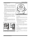
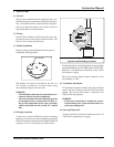
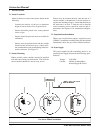
5.4 Calibration Procedure
Routine calibrations are easily performed using the
magnetic tool provided with each sensor.
Briefly hold the magnet tool close to the small dot
located on the lower edge of the front panel. The
arrow on the upper left side of the LED will illuminate
and the 4-20 mA output is locked at 1.5 mA, indicating
that the sensor module is ready for calibration. Sim-
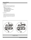
ply expose the sensor to a ZERO gas and observe the
L.C.D. readout. In normal situations, simply exposing
the sensor to an atmosphere free of the gas of interest
is satisfactory. If it does not return to the correct
ZERO reading, a ZERO adjustment is required. Hold
the magnet close to the UP ZERO or DOWN ZERO
indicators and adjust the reading to the correct ZERO
reading.
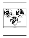
Connect the calibration adapter and expose the sen-
sor to an appropriate SPAN gas using a span mixture
containing a known concentration of the gas of inter-
est at a minimum flow rate of 300 cc/minute. (Use per-
meation tube for 4105-25) Allow 3-5 minutes before
making any adjustments.
If the L.C.D. does not display the correct SPAN value,
a SPAN adjustment is required. With the arrow still
flashing, hold the magnet close to the UP SPAN or
DOWN-SPAN indicators and adjust the reading to the
correct SPAN value. (The 4-20 mA out is automati-
cally adjusted.)
The monitor is now calibrated. Deactivate calibration
by holding the magnet close to the small dot again.
This releases the 1.5 mA lock.
5.5 Fault Identification
A Fault condition is detected if the sensor output drifts
far enough negative to cause the 4-20 mA output to
reach 1.5 mA (±15% of full scale) or the sensor failure.
The sensor module demonstrates that a fault condi-
tion exists by illuminating the RED LED on the front
panel and by holding the 4-20 mA output at 0 mA.
These conditions will exist until the fault is corrected.
Table 4.1
Calibration Span Gas Flow Rates