


16
Operation
CONSOLE CALIBRATION
(CONTINUED)(CONTINUED)
(CONTINUED)(CONTINUED)
(CONTINUED)
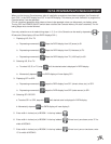
6. Recheck the new Speed Cal numbers. Zero out Distance display as in step 3. Enter the new Speed Cal
number as in step 1. Repeat steps 4 and 5.
MEASURE CAREFULLY. Be sure tire is properly inflated before measuring. Measure tire in type
of soil in which you will be spraying. Circumference of tire will vary when measured in soft soil
versus hard packed soil. For best results, measure several times and average the results. Re-
measure periodically.
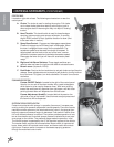
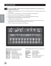
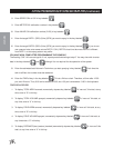
CALCULATING “METER CAL”
The Flow Meter calibration number is stamped on the label attached to each Flow Meter; this number is to be
used for gallon per area applications. To convert original METER CAL from gallons to desired units of measure
(oz., lbs or liters per area) see Abbreviations and Conversions section of this manual. Write down this calibra-
tion number for future reference when programming the console.
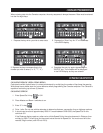
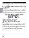
CALCULATING "VALVE CAL”
The initial Control Valve calibration number is 2123. After operating the system, you may desire to refine this
number. See definitions below.
Valve Backlash Controls the time of the first correction pulse after a change in correction direction is detected.
Incr to Decr or Decr to Incr Range: 1 to 9, 1-Short Pulse, 9-Long Pulse
Valve Speed Digit Controls the Speed of the Control Valve motor.
Running the Control Valve too fast will cause the system to oscillate.
Range: 1 to 9, 1-slow, 9-Fast
Brake Point Digit Percent Sets the point at which the Control Valve motor begins braking, so as not to over
shoot the desired rate. Digit is percent away from target rate. Range: 0 to 9, 0=5%, 1=10%, 9=90%,
Deadband Digit Allowable difference between target and actual application rate, where rate correction is not
performed. Range: 1 to 9, 1 = 1%, 9 = 9%
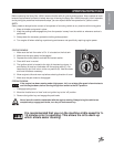
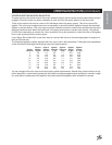
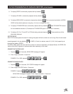
CALCULATING "RATE 1 AND RATE 2 CAL" (See Spraying Procedure section)
Determine the application rate at which your chemical should be sprayed. Consult with your Dealer to insure
your spray nozzles are capable of applying at this target rate.
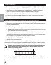
Using CAPACITY = .35 GPM (1.67 lit/min) and pressure = 30 PSI (20 bar) you would select tip number
XR8004 from the Nozzle Charts Section, since it comes closest to providing the desired output.
VERIFYING FLOW RATE LIMITS
The flow rate of the sprayer must be within the range of 1 to 55 GPM (4 to 210 lit/min).