


28
Spraying Procedure
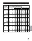
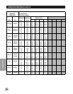
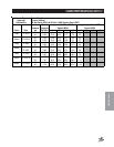
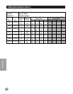
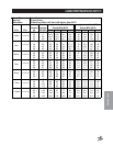
THE NOZZLE CHART METHOD OF CALIBRATION
The Nozzle Chart Method is useful when the sprayer nozzles are new or nearly new. It is also the most useful
method to employ when the sprayer is equipped with an Electronic Spray Control System. The Electronic Spray
Control System does most of the calibration work, it is up to the operator to select the proper combination of
nozzle size and ground speed which will deliver the desired application rate.
The nozzle chart method requires the use of the appropriate nozzle charts which are found in the back of this
manual (Nozzle Charts 1 through 8). Nozzle charts for other nozzles are available from the manufacturer.
CALIBRATION STEPS
1. Determine “HOW” your sprayer is to be calibrated from the list of variables below.
a. Nozzle Type (Teejet, Turbo Turf, Turbo Flood)
b. Spacing (10" (25 cm) or 20" (51 cm) or 30" (76 cm))
c. Expression of Application Rate (gpa or gpt or lph)
The answers to these three questions will direct you to the appropriate nozzle chart for your application.
The correct nozzle chart MUST be used.
2. Determine the Desired Application Rate.
This is determined from the information on chemical labels or other technical information available from
a variety of sources.
3. Determine an Acceptable Ground Speed.
Conditions over which the sprayer will operate generally dictate the appropriate ground speed. Within the
limits of practicality and efficiency, spraying should generally be done at lowest possible speed. This
increases operator safety and contributes to more precise application of chemicals. For example, golf
greens and tees and hill areas would generally be sprayed in the range of 2
1
/2 to 3
1
/2 mph (4-6 kph).
Larger, open and more level areas such as golf fairways and park or school grounds would be sprayed at
4
1
/2 to 6 mph (7-10 kph).
The vehicle which carries or tows the sprayer should be equipped with a precise low-speed speedom-
eter. If it is not, exact ground speed at a given engine speed must be determined by timing the travel of
the sprayer over a measured distance.
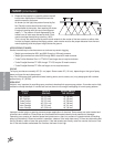
4. Determine Nozzle Size.
Refer to the appropriate nozzle chart in the back of this manual for your nozzle TYPE (the type of nozzle
you have or type you wish to use), nozzle SPACING and CALIBRATION TYPE (gpm, gpt or lph).
You will note from the chart, that application rates from any given nozzle decrease as the ground speed
increases. In other words, the faster you drive, the less material you are applying.
Application rates are shown in the columns to the right of the charts. Once the desired application rate is
decided upon, it should be located, as nearly as possible in one of these columns on the appropriate
chart for your operation. It could well be that the approximate rate desired would be obtained from the
nozzles already installed in the boom. If this is not possible, then nozzles will need to be changed.
When selecting a new nozzle size refer to the “Discharge Rate Column” on the nozzle charts.
The Discharge Rate (gpm or lpm) multiplied by the number of nozzles should not exceed 75%
of the actual discharge volume of the sprayer pump. [i.e., if you need to use nozzles which
discharge 0.8 gpm (3.0 lpm), and the spray boom is equipped with 12 nozzles, the sprayer
pump would have to produce an actual discharge volume of 13 gpm (49 lpm) in order to
properly supply these nozzles.] If the collective volume of the spray boom nozzles exceeds the
actual discharge volume of the pump, inadequate pressure and poor nozzle distribution
patterns may result.
Once nozzle type and size have been determined, those nozzles are installed in the sprayer boom.
Nozzles should be expected to be replaced after 15-20 hours of actual sprayer operation. After nozzles
are installed, make trial application of water over a known area to check application rate.