


For Machines Mfg. Since 8/09 Model SB1020
-19-
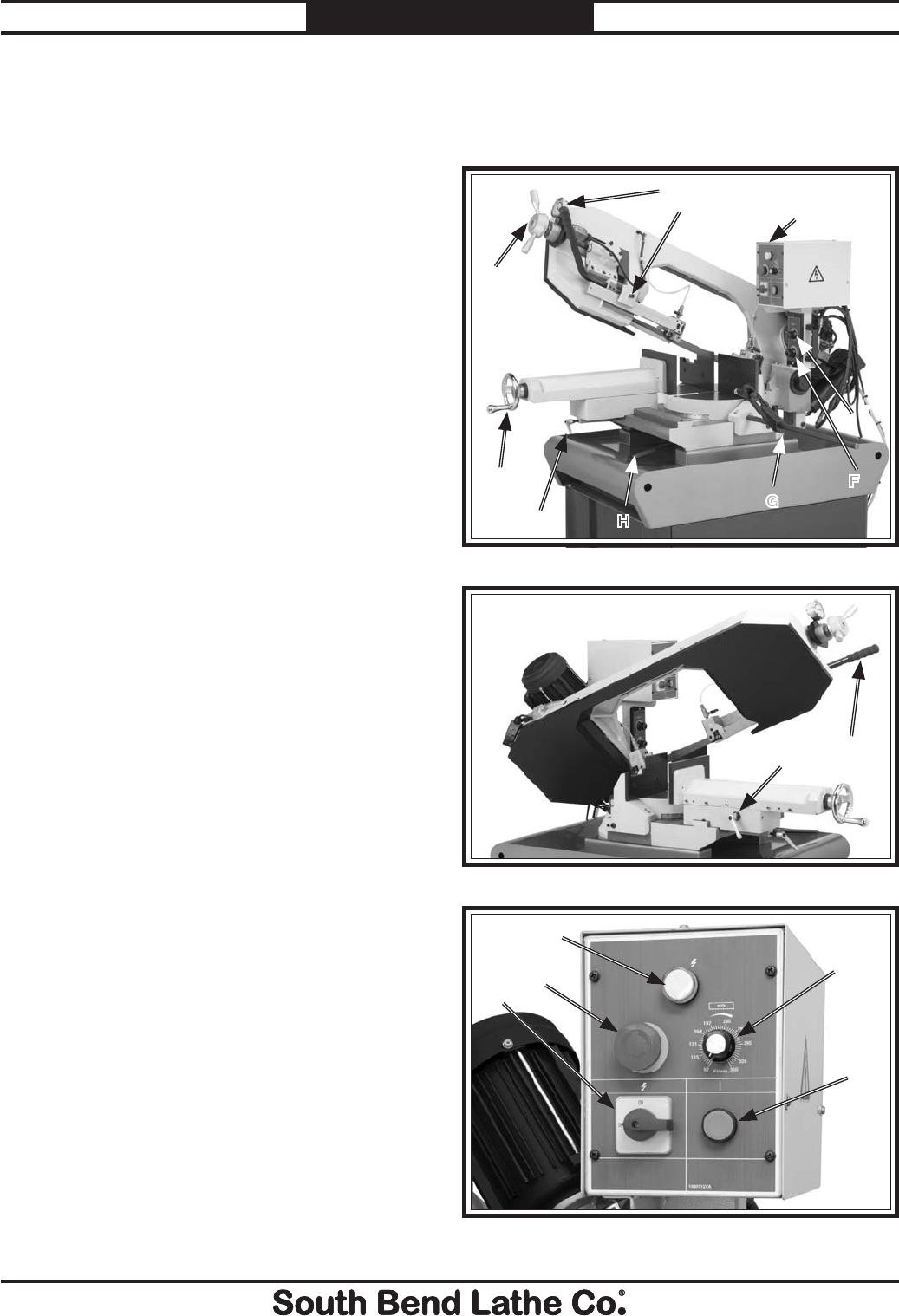
OPERATION
Description of Controls
& Components
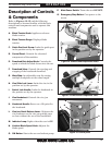
Refer to Figures 13–15 and the following
descriptions to become familiar with the basic
controls and components used to operate this
machine.
A. Blade Tension Knob: Applies or releases
blade tension.
B. Blade Tension Gauge: Displays blade
tension.
C. Guide Post Lock Screw: Locks the guide post
in the position set by the operator.
D. Control Panel: Controls the electrical
components of the machine.
E. Downfeed Rate Adjust Knob: Controls the
speed at which the blade lowers into the cut.
F. Downfeed Valve: Controls the starting and
stopping of the headstock downfeed.
G. Work Stop: An adjustable stop for cutting
multiple workpieces at the same length.
H. Vise Slide Lock Lever: Locks the vise in the
position set by the operator.
I. Swivel Lock Handle: Locks the headstock in
the position set by the operator.
J. Vise Handwheel: Controls the vise jaw
movement.
K. Headstock Handle: Serves as a lift-point for
the headstock.
L. Vise Jaw Quick Release Lever: Releases the
vise leadscrew so the vise can quickly open
or close without the use of the handwheel.
M. Indicator Lamp: Lights when the saw is ON.
N. Variable Blade Speed Knob: Adjusts the
blade speed.
O. ON Button: Starts the saw and coolant pump.
K
L
Figure 14. Controls and components (rear).
A
H
I
J
G
F
B
C
D
E
Figure 13. Controls and components (front).
M
N
P
Q
O
Figure 15. Control panel.
P. Main Power Switch: Turns the saw ON/OFF.
Q. Emergency Stop Button: Cuts power to the
motor.