For Machines Mfg. Since 8/09 Model SB1040/SB1041
-49-
ELECTRICAL
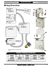
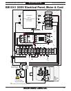
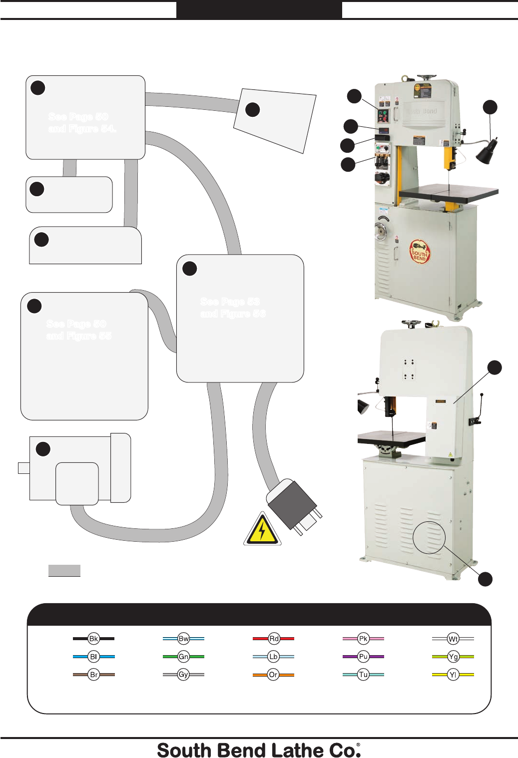
Wiring Overview
WELDING UNIT
MOTOR
WELDER’S
LAMP
CONTROL
PANEL
A
B
FPM
DISPLAY
B
C
C
E
F
G
G
F
D
ELECTRICAL
PANEL
E
WORK
LAMP
A
D
May Represent Multiple Wires
*
See Page 50
and Figure 54.
See Page 50
and Figure 55
See Page 53
and Figure 56
See Page 53
and Figure 53
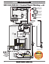
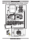
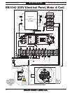
The photos and diagrams included in this section are best viewed in color. You can
see them in color at www.southbendlathe.com.
BLACK
WHITE
GREEN
RED
BLUE
BROWN
GRAY
ORANGE
YELLOW
YELLOW
GREEN
PURPLE
PINK
LIGHT
BLUE
BLUE
WHITE
TUR-
QUIOSE
NOTICE:
WIRING DIAGRAM COLOR KEY


