


STUDER Innotec Xtender
Installation and operating Instructions Xtender V1.3 Page 10
vehicles and leisure vehicles. In these cases, two separate AC inputs are often required, one
connected to the grid and the other connected to an on-board generator. Switching between two
sources must be carried out using an automatic or manual reversing switch, conforming to the
applicable local regulations. The Xtender has a single AC input.
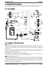
Various application examples are described in figs. 10a – 10b – 10c).
4.1.4
M
ULTI
-
UNIT SYSTEMS
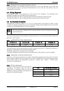
Whatever system is selected, it is possible to realise systems composed of several units of the same
type and the same power output. Up to three Xtenders in parallel or three extenders forming a
three-phase grid or three times two with three Xtenders in parallel forming a three-phase / parallel
grid, may be thus combined.
4.2 Earthing system
The Xtender is a protection class I unit, which is intended for cabling in a grid type TT, TN-S or TNC-
S. The earthing of the neutral conductor (E) is carried out at a sole installation point, upstream of the
RCD circuit breaker (D).
The Xtender can be operated with any earthing system. In all cases it is imperative that the
protective earth be connected in compliance with the applicable standards and regulations. The
information, notes, recommendations and diagram mentioned in this manual are subject to local
installation regulations in every case. The installer is responsible for the conformity of the installation
with the applicable local standards.
4.2.1
M
OBILE INSTALLATION OR INSTALLATION CONNECTED TO THE GRID VIA PLUG CONNECTOR
When the input of the device is connected directly to the grid via a plug, the length of the cable must
not exceed 2 m and the plug must remain accessible.
In the absence of voltage at the input, the neutral and live are interrupted, thereby guaranteeing
complete isolation and protection of the cabling upstream of the Xtender.
The earthing system downstream of the Xtender is determined by the upstream earthing system
when the grid is present. In the absence of the grid, the earthing system downstream of the inverter
is in isolated mode. The safety of the installation is guaranteed by the equipotential bonding.
The connection (link) between the neutrals (C) upstream and downstream of the Xtender is
not permitted in this configuration.
This connection type guarantees the optimal continuity for supplying the Xtender loads. The first
isolation fault will not lead to an interruption in the supply.
If the installation requires the use of a permanent isolation controller this would have to be de-
activated when the TT network is present at the Xtender input.
All sockets and protection class I devices connected downstream of the Xtender must be
properly connected to the earth (earthed socket). The cabling rules above remain valid,
including fixed installations, in all cases where the Xtender input is connected to the grid via
a plug connector.
4.2.2
F
IXED INSTALLATION
The installation may be equivalent to a mobile installation (with interrupted neutral).
In a fixed installation where the neutral is connected to the earth at a single installation point
upstream of the Xtender, it is permissible to carry out a connection of the neutrals in order to
preserve an unchanged earthing system downstream, independent of the operating mode of the
Xtender. This choice has the advantage of keeping the protection devices downstream of the
Xtender. This connection can be executed according to the examples in appendix 1, or carried out
by modifying the configuration {1486}
In this case the appearance of the first fault will lead to the installation stopping or the disconnection
of the protection devices upstream and/or downstream of the Xtender.
Safety is guaranteed by the equipotential bonding and by any RCD circuit-breakers placed
downstream.