


STUDER Innotec Xtender
Installation and operating Instructions Xtender V1.3 Page 15
The length of the communication bus cable must not exceed 300 m.
In a system comprising a single Xtender, the connection of the RCC-02 or RCC-03 may be
conducted without stopping the Xtender (warm).
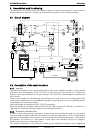
The communication bus will be used to interconnect other Xtender inverters in the case of a multi-
unit application or to connect other types of users who have the proprietary protocol of Studer
Innotec. In these cases, the installation must be switched off using the main “ON/OFF” button (1) to
connect the units via the communication bus.
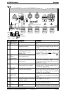
The 2 switches of terminal of the communication bus, “Com. Bus" (4) both
remain in
position T (terminated) except when both
connectors are in use. In this case, and only in
this case, both must be placed in the O open position. If one of the two connectors is not
in use, the two termination switches (14) will be in position T.
4.5.10
CONNECTING THE TEMPERATURE SENSOR
(BTS-01)
The temperature sensor, BTS-01 is supplied with a 3 m cable fitted with RJ11/6-type plugs. It may
be connected or disconnected at any time (including when the device is in use) using the
corresponding socket (2) marked “Temp. Sens.” on the Xtender. Plug the connectors into the
socket (2) until they click in. The temperature sensor sleeve may simply be stuck onto the battery or
directly next to it. The temperature sensor will be recognised automatically and the correction made
immediately.
5 Powering up the installation
It is imperative that the closing cap for the connection compartment be installed and
screwed tight before the installation is energised. There are dangerous voltages within the
interior of the connection compartment.
The connection of the Xtender must be carried out in the order given below. Any disassembly must
be carried out in the reverse order.
1.
Connecting the battery
Too high or inappropriate a battery voltage may seriously damage the Xtender. For
example, installing a 24 V battery in the Xtender 3000-12.
If the Xtender has been connected the wrong way around by accident (incorrect polarity of
the battery) it is highly likely that the protection fuse on the battery cable may melt and will
have to be replaced. If such is the case, it will be necessary to disconnect all the
connections to the Xtender including the battery. If, after replacing the fuse, the Xtender
proves not to work correctly after reconnecting the battery with the correct polarity, it will
have to be returned to your distributor for repair.
2.
Putting the Xtender(s) in operation
using the main ON/OFF switch (1). The Xtender is
supplied and is ready for operation. If you require immediate start-up of the inverter when the
battery is powered up, the main switch (1) must be in the “ON” position and the
configuration {1111} activated.
3.
Connecting the consumers at the output
: Activate the output protection device (F) if existing,
and/or press the ON/OFF button (41). The light indicator “AC out” (46) lights up or flashes (in
the event of an absence of consumers).
4.
Activating the input circuit breaker(s) (H)
If an AC source (generator or electrical grid) valid in
frequency and voltage is present at the AC input, the device automatically goes into transfer
and will start to charge the batteries. The consumers at the output are therefore supplied
directly by the power source present at the input.
Your installation is now in operation. If particular configuration or adjustment is required by the
system, it is recommended to carry this out immediately. Adjustments must be made with the RCC-
02/03 remote control. Please refer to the operating instructions for this accessory.