


STUDER Innotec Xtender
Installation and operating Instructions Xtender V1.3 Page 12
4.3.4
D
IMENSIONING THE ALTERNATIVE ENERGY SOURCES
In a hybrid system, the alternative energy sources such as the solar generator, wind power and
small hydropower should, in principle, be dimensioned in such a way as to be able to cover the
average daily consumption.
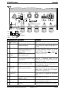
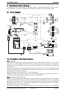
4.4 Wiring diagrams
The diagrams shown in the appendix of this document are subsidiary. The applicable local
installation regulations and standards must be adhered to.
The elements referred to with an uppercase letter denote the alternate current (AC) part.
The elements referred to with a lowercase letter denote the direct current (DC) part.
4.5 Connecting the battery
Lead batteries are usually available in 2 V, 6 V or 12 V block types. In the majority of cases, in order
to obtain an operating voltage that is correct for Xtender usage, several batteries must be connected
in series or in parallel depending on the circumstances.
In multi-unit systems, all Xtenders from the same system must be connected according to
the same battery bank.
The various cabling options are presented in figures 5a-5b (12 V), 5c-5e (24 V) and 6a to 6d (48 V) in
appendix I of this manual.
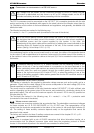
4.5.1
M
INIMUM BATTERY CABLE CROSS
-
SECTION
XTH3000-12
XTH5000-24
XTH6000-48
XTH8000-48
90 mm
2
90 mm
2
70 mm
2
90 mm
2
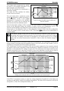
The cable sections recommended above are valid for lengths less than 3 m. beyond this length it is
strongly recommended to over-section the battery cables.
The battery cables must also be as short as possible.
It is always preferable to keep the cable at the negative pole of the battery as short as possible.
4.5.2
C
ONNECTING THE BATTERY
(X
TENDER SIDE
)
Insert the conduit glands supplied on the battery cable before tightening the cable clamp. Crimp the
cable clamps and fasten the conduit gland on the device. Repeat this for the second battery cable.
Fix the battery cables to the appropriate connections „+ Battery “and „- Battery “. The M8 screws
must be very well tightened.
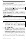
4.5.3
DC
INPUT PROTECTION
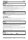
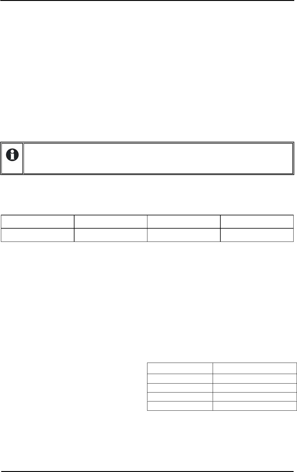
In order to avoid any further loss and protection
redundancy, the Xtender does not have an
internal fuse. A protection device (f) must be
installed as close as possible to the battery and
sized as per the table opposite:
Unit
Fuse on the battery side
XTH-3000-12
400 A
XTH-5000-24
350 A
XTH-6000-48
250 A
XTH-8000-48
300 A