


STUDER Innotec Xtender
Installation and operating Instructions Xtender V1.3 Page 22
6.3 Multi-unit configurations
Several Xtenders can be used in the same system, either to create a three-phase system or to
increase the power output of a single or two phases. The implementation of this configuration
requires particular precautions and it must be installed and commissioned by qualified personnel
only.
When multi-unit system is commissioned, the software's version of every units will be
automatically checked and units may refuse to start in case of incompatibility. If so, an
upgrade of every units is be required with the RCC-02/03 and the last software version
available by the manufacturer. (Read the RCC-02 user's manual to perform this operation).
The inverters selected must be of the same type and the same rated power output. There is a
shared battery bank.
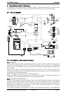
In these multi-unit system, the units must be interconnected via a communication bus connected to
the connectors (3) by cable (art. no. CAB-RJ45-2) of a maximum length of metres. Interrupting this
connection in a multi-unit system will lead to the stoppage – after 5 seconds – of all the units in the
system.
Various application examples are described from fig. 12 to fig. 19 of Appendix I.
It is important to read and adhere to the descriptions associated with each of the figures
mentioned above
In multi-unit system,it is not recommended to employ the manual setting {1532} of the LVD
dynamic correction.
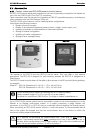
In configurations carrying several Xtenders, each unit is controlled independently using the ON/OFF
push button (41). When the on/off control is given via the RCC-02/03 remote control, it is applied
simultaneously to all units.
6.3.1
T
HREE
-
PHASE SYSTEM
Three Xtenders of the same type can be used and combined in order to establish a three-phase grid.
An example of cabling in three-phase is given at figs. 13.-14.
When 3 Xtenders are cabled to form a three-phase grid, the cabled phases at the input determine
the jumper position for selecting the phase (10). It is vital to determine and select the phase for each
Xtender. If the grid is not available at the input of the master unit (phase 1), all the units of the system
will switch to inverter mode. If only a single-phase source is available, it must be connected to phase
1. The other two phases will therefore be supplied by the other two working units in inverter mode.
6.3.2
I
NCREASING THE POWER AND CONNECTION IN PARALLEL
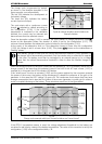
Up to three Xtenders can be cabled in parallel in order to increase the system’s rated power output.
In this configuration, all the ACin inputs of the Xtender must be cabled. One of the units functions as
master and will decide on the operation or suspension of the units in parallel according to the
consumer’s power demand. The yield of the installation is therefore still optimal.
An example of parallel connection is given in fig.12. and the comments on p. 27.
6.3.3
C
OMBINED SYSTEM
It is possible to combine a three-phase system with one or several phases made up of 2 or 3
Xtenders in parallel. An example of cabling is given at fig. 15.
It is therefore possible to combine up to nine Xtenders by running three Xtenders parallel in a three-
phase grid. Examples of cabling are given in figs. 16 to 18 and the comments on p. 27.
When the load search sensitivity {1187} is set to 0 in a paralleled multi-units system, the
master/slave behaviour is inhibited and all the inverter will be always functional whatever the
load is.