


STUDER Innotec Xtender
Installation and operating Instructions Xtender V1.3 Page 9
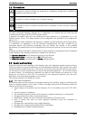
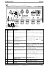
12 -BAT Negative pole battery
connection terminals
and when tightening the clamp.
13 AC Input Connection terminals for the
alternative power supply
(generator or public network)
See chapter 4.5.7 - p. 14.
Note: It is imperative that the PE terminal
be connected.
14 AC Output Connection terminals for the
device output.
See chapter 4.5.6 - p. 14.
Note: Increased voltages may appear on
the terminals, even in the absence of
voltage at the input of the inverter.
4 Cabling
The connection of the Xtender inverter / charger is an important installation step.
It may only be carried out by qualified personnel and in accordance with the applicable local
regulations and standards. The installation must always comply with these standards.
Pay attention that connections are completely tightened and that each wire is connected at the right
place.
4.1 Choice of system
The Xtender may be used in different system types, each of which must meet the standards and
particular requirements associated with the application or site of installation. Only an appropriately
qualified installer can advise you effectively on the applicable standards with regard to the various
systems and the country concerned.
Examples of cabling are presented in appendix I of this manual, fig. 5 and following. Please carefully
read the notes associated with these examples in the tables on p. 27 and following.
4.1.1
H
YBRID TYPE STAND
-
ALONE SYSTEMS
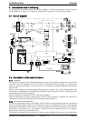
The Xtender can be used as a primary supply system for grid-remote sites where a renewable
energy source (solar or hydraulic) is generally available and a generator is used as backup. In this
case, batteries are generally recharged by a supply source such as solar modules, wind power or
small hydropower systems. These supply sources must have their own voltage and/or current
regulation system and are connected directly to the battery. (Example, fig. 11)
When the energy supply is insufficient, a generator is used as a back-up energy source. This allows
the batteries to be recharged and direct supply to consumers via the Xtender transfer relay.
When the input voltage source is a low power generator (lower than the Xtender power) the
factory settings (adapted to grid-connection) must be modified according to the
“generator” column in the configuration table on p. 34.
4.1.2
G
RID
-
CONNECTED EMERGENCY SYSTEMS
The Xtender can be used as an emergency system, also known as an uninterruptible power supply
(UPS) – enabling a reliable supply to a site connected to an unreliable network. In the event of an
interruption to the energy supply from the public network, the Xtender, connected to a battery,
substitutes the faulty source and enables a support supply to the users connected downstream.
These will be supplied as long as the energy stored in the battery allows. The battery will quickly be
recharged at the next reconnection to the public grid.
Various application examples are described in figs. 8a – 8c in appendix I.
The use of the Xtender as a UPS must be carried out by qualified personnel who have
been checked by the responsible local authorities. The diagrams in the appendix are given
for information and as a supplement. The applicable local standards and regulations must
be adhered to.
4.1.3
I
NTEGRATED MOBILE SYSTEMS
These systems are meant to be temporarily connected to the grid and ensure the supply of the
mobile system when this is disconnected from the grid. The main applications are for boats, service