Maintenance
THS710A, THS720A, THS730A & THS720P Service Manual
6–25
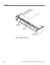
Installation. Use this procedure to reassemble the entire instrument.
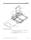
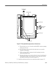
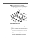
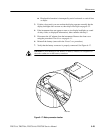
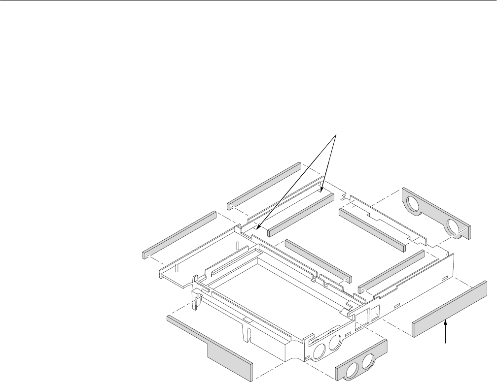
1. Check that the ten foam pads on the chassis are correctly installed. The foam
pads that surround the display module should be aligned to locating marks in
the chassis. Refer to Figure 6–15 for the locations of all the foam pads.
Typical locating marks
Align this foam pad with
bottom edge of chassis
Figure 6–15: Foam pad locations on the chassis
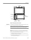
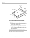
2. Place the main board on a soft, static-free surface with the two metal shields
facing up and away from you.
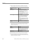
3. Install the inverter board cable (either end) into its connector (J7) on the
main board.
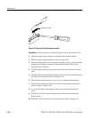
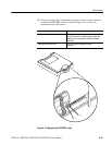
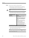
4. To reconnect the switch flex-circuit assembly to the main board, follow these
steps:
a. Hold the switch flex-circuit assembly upright with the carbon contacts
facing you.
b. Use both thumbs and forefingers to grasp the left and right sides of the
connector.
c. From both sides, push the connector into its socket. You may need to
alternate pushing on the left and right sides to insert the connector.


