


6
Installation
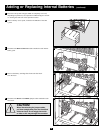
UPS LOCATION
Move your UPS over short distances using its wheels. NOTE: the wheels are not designed to provide long-term support for the UPS system after final
installation. Mounting bracket installation is required.
DANGER!
RISK OF PRODUCT DAMAGE AND SERIOUS PERSONAL INJURY
The UPS System's wheels are not designed to provide long-term support for the UPS system after final
installation.
MOUNTING BRACKET INSTALLATION IS REQUIRED.
If the mounting brackets are not installed, the
wheels may eventually fail and potentially damage the UPS System and cause serious personal injury.
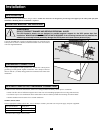
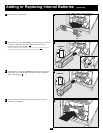
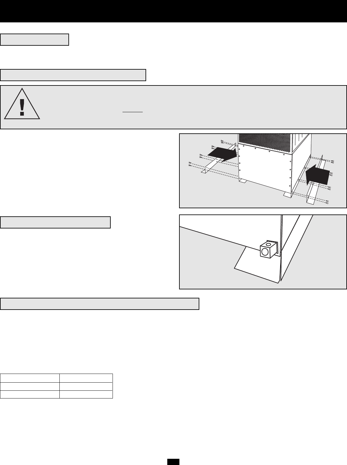
MOUNTING BRACKET INSTALLATION
Using the included bolts, install one mounting bracket on each side of the
UPS System as shown. If desired, install the bracket to the floor surface
with user-supplied hardware.
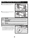
GROUNDING CONNECTION
Using a user-supplied 4 AWG ground wire, connect the UPS System's
ground lug to earth ground. Tighten connections with a torque of not less
than 35 inch-lbs. (3.9 NM). Keep ground wire connected at all times after
installation.
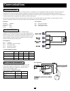
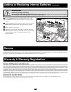
UPS INPUT AND OUTPUT HARDWIRE CONNECTION
In addition to the instructions listed below, follow all warnings found in the Safety section prior to connection.
• Install with flex cable of sufficient length to move UPS clear of surrounding equipment for servicing (sides and rear).
• Use ferrule caps to cover termination cables connected to UPS to avoid frayed ends from shorting on terminal block.
• Neutral conductor must be same size as current conductors.
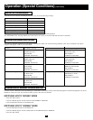
WIRING SELECTION
Choose appropriate cabling (rated VW-1, FT-1 or better) to connect your UPS to an AC power supply and your equipment.
UPS System Model Wiring Size
20kVA 6 AWG / 14 mm
2
30kVA 4 AWG / 22 mm
2
Maximum Cable Length: 10 m (32.8 ft)
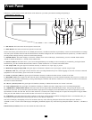
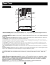
Front View
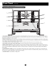
Rear View