8
Operation (Normal Conditions)
(continued)
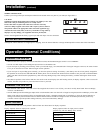
LCD DISPLAY SELECT BUTTON
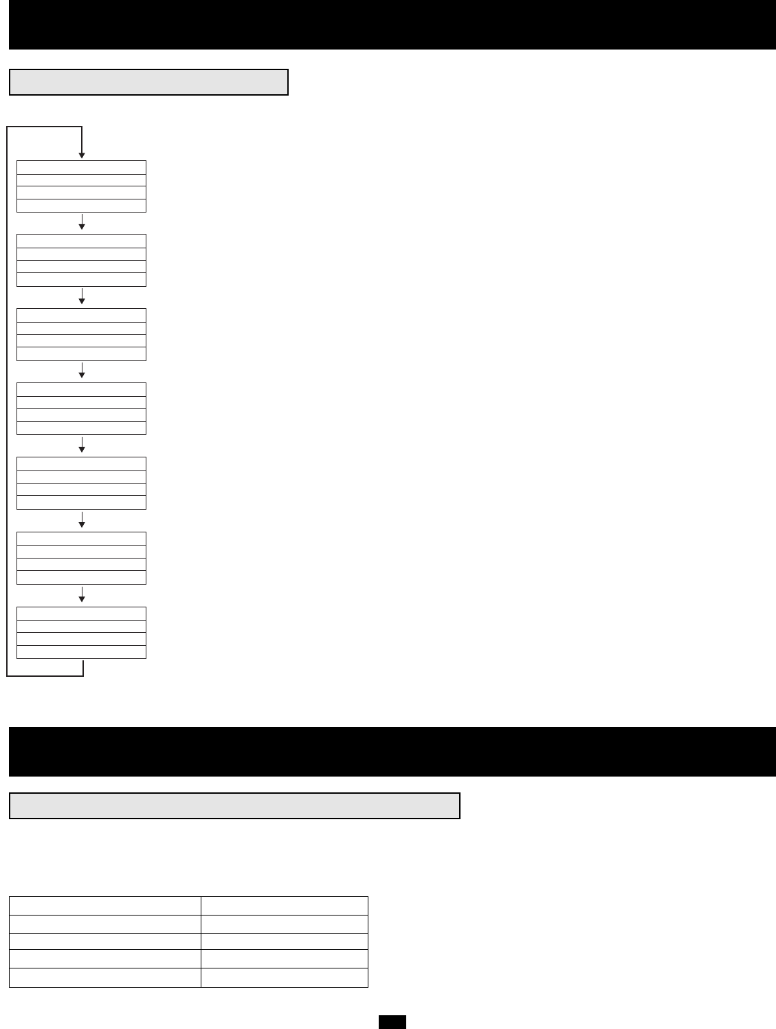
Momentarily press the “SELECT” button on the front panel to browse through different power readings on the LCD Display.
BYPASS OUTPUT
R: XXXV R: XXX.XV
S: XXXV S: XXX.XV
T: XXXV T: XXX.XV
(Bypass & Output Voltage)
OUTPUT LOAD
R: XXX% XXX.XA
S: XXX% XXX.XA
T: XXX% XXX.XA
(Output Load & Current)
MAINS INVERTER
R: XXXV R: XXX.XV
S: XXXV S: XXX.XV
T: XXXV T: XXX.XV
(Mains & Inverter Voltage)
BYPASS: XX.X Hz
MAINS: XX.X Hz
OUTPUT: XX.X Hz
INVERTER: XX.X Hz
(Bypass, Mains, Output & Inverter Frequency)
(Charger Mode, Charger/Battery Voltage & Battery Percentage)
(Serial Number, DC BUS Voltage, Temperature & Firmware Version)
(Button Functions)
CHARGE FLOATING
CHARGER: XXX.XV
BATTERY: XXX.XV
BATTERY: XXX.X%
SN: XXX
DC BUS: XXV - XXV
TEMP: XXX.X˚C
VERSION: XXX
ON: UPS START
OFF: UPS BYPASS
SEL: UPS MESSAGE
ENT: SET UPS
Press "SELECT" Button
Press "SELECT" Button
Press "SELECT" Button
Press "SELECT" Button
Press "SELECT" Button
Press "SELECT" Button
Press "SELECT" Button
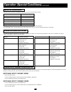
Operation (Special Conditions)
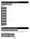
OPERATION ON BYPASS—VOLTAGE OUT OF RANGE
While in Bypass Mode, the UPS monitors the input voltage, which on Bypass equals the output voltage. If the output voltage passes out of an acceptable
range (between 15% higher and 20% lower than nominal), the UPS displays the condition on its LCD and stops supplying output power to its load. If
power levels return to an acceptable level, the UPS resumes supplying power to the load, and its LCD reports that output voltage was too high or too
low at one time, but has returned to nominal.
Bypass Voltage Condition LCD Display Message
>15% Higher than Nominal BYPASS HI NO O/P
>20% Lower than Nominal BYPASS LO NO O/P
Was Too High, Now Nominal BYPASS WAS HI
Was Too Low, Now Nominal BYPASS WAS LO


