


4A
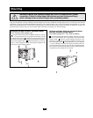
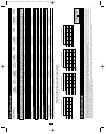
Feature Identification
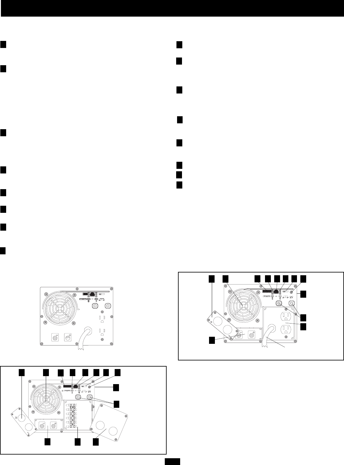
Identify the premium features on your specific model and quickly locate instructions on how to maximize their use.
Configuration DIP Switches: optimize Inverter/Charger
operation depending on your application. See pages 6-7 for
setting instructions.
Operating Mode Switch: controls Inverter/Charger operation.
The “AUTO/REMOTE” setting ensures your equipment
receives constant, uninterrupted AC power. It also enables the
Inverter/Charger to be remotely monitored and controlled with
an optional remote module (Tripp Lite model APSRM4, sold
separately or included with select models). The “CHARGE
ONLY” setting allows your batteries to return to full charge
faster by turning the inverter off which halts battery discharging.
See page 5 for setting instructions.
Operation Indicator Lights: intuitive “traffic light” signals
show whether the Inverter/Charger is operating from AC line
power or DC battery power. It also warns you if the connected
equipment load is too high. See page 5 for instructions on reading
indicator lights.
Battery Indicator Lights: intuitive “traffic light” signals show
approximate charge level of your battery. See page 5 for
instructions on reading indicator lights.
DC Power Terminals: connect to your battery terminals. See
page 10 for connection instructions.
AC Receptacles (not on hardwire models): allow you to connect
equipment that would normally be plugged into a utility outlet.
AC Input Cord (not on hardwire models): connects the
Inverter/Charger to any source of utility- or generator-supplied AC
power. See page 11 for connection instructions.
Hardwire AC Input/Output Terminal Strip (not on corded
models): securely connects the Inverter/Charger to facility or
vehicle electrical system. See page 11 for connection instructions.
Resettable Circuit Breakers: protect your Inverter/Charger
against damage due to overload. See page 5 for resetting instructions.
Remote Control Module Connector: allows remote monitoring
and control with an optional module (Tripp Lite model
APSRM4, sold separately or included with select models). See
remote module owner’s manual for connection instructions.
Battery Charge Conserver (Load Sense) Control (available
on select models): conserves battery power by setting the
low-load level at which the Inverter/Charger’s inverter automat-
ically shuts off. See page 7 for setting instructions.
Main Ground Lug: properly grounds the Inverter/Charger to
earth ground or to vehicle or boat grounding system. See page
10 for connection instructions.
Thermostatically-Controlled Cooling Fan: quiet, efficient fan
regulates internal temperature and prolongs equipment service life.
Fan runs intermittently depending on temperature and load.
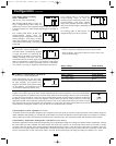
DC Power Terminal Cover Plate
Hardwire AC Input/Output Cover Plate
Battery Temperature Sensing Connector (available on select
models): prolongs battery life by adjusting charge based on battery
temperature. Use with cable (included on select models). See page
7 for details.
Voltage Regulation Indicator Lights (available on select models):
shows when the Inverter/Charger is automatically “boosting”
abnormally low AC voltage or “cutting” abnormally high AC voltage
without relying on battery power. This function is automatic and
requires no action on the user’s part.
Redundant Switch/Indicator Light Panel (available on select
models): additional top mounted switch/indicator light panel allows
easy control and monitoring when Inverter/Charger is vertically mounted.
1
2
3
4
5
6
7
8
9
10
11
12
13
14
15
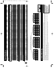
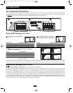
Front View (1012 Corded Models)
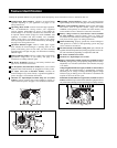
HOT IN
NEUTRAL IN
GROUND IN
GROUND OUT
HOT OUT
“FOR USE WITH COPPER WIRE ONLY”
NEUTRAL OUT
1 24 3
5
6
9
10
111314
1
24 3
5
9
10 111314
8 15
Front View (All Hardwire Models except APS3624VR).
16
16
Side Mounted, Not Shown
16
Side Mounted, Not Shown