


6A
Configuration
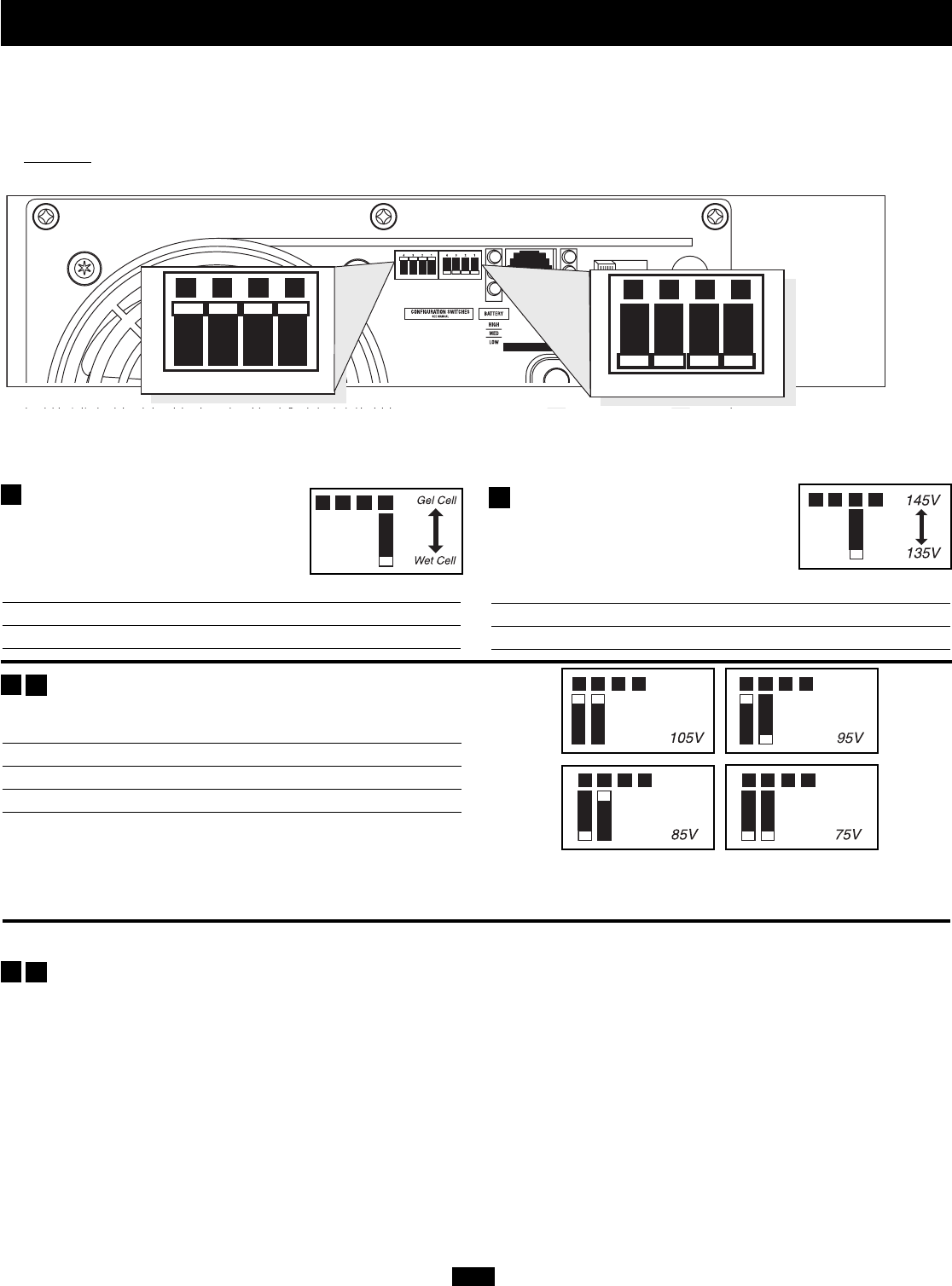
Select Battery Type—REQUIRED
CAUTION: The Battery Type DIP Switch setting must
match the type of batteries you connect, or your batteries
may be degraded or damaged over an extended period of
time. See “Battery Selection,” p. 8 for more information.
Battery Type Switch Position
Gel Cell (Sealed) Battery Up
Wet Cell (Vented) Battery Down (factory setting)
Select High AC Input Voltage Point
for Switching to Battery—OPTIONAL*
Voltage Switch Position
145V Up
135V Down (factory setting)
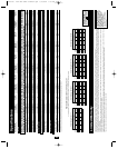
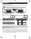
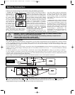
Set Configuration DIP Switches
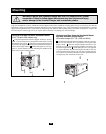
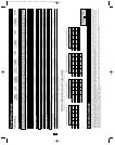
Using a small tool, set the Configuration DIP Switches (located on the front panel of your unit, see diagram) to optimize Inverter/Charger
operation depending on your application. 612, 750 and 1250 models have one set of four DIP Switches (Group A). All other models include
an additional set of four DIP switches (Group B) to configure additional operational functions.
A1A2A3A4
INPUT C/B 10A
OUTPUT C/B 12A
B4 B3 B2 B1
A4 A3 A2 A1
Group B Dip Switches (Select Models)
Group A Dip Switches (All Models)
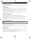
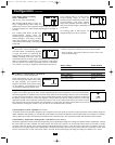
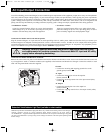
Group A DIP Switches (All Models)
Select Low AC Input Voltage Point for Switching to
Battery—OPTIONAL*
Voltage Switch Position
105V #A4 Up & #A3 Up
95V #A4 Up & #A3 Down
85V #A4 Down & #A3 Up
75V #A4 Down & #A3 Down
(factory setting)
* Most of your connected appliances and equipment will perform adequately when your Inverter/Charger’s High AC Input Voltage Point is left in the factory setting and its Low AC Voltage Input
Point is set to 95V. However, if the unit frequently switches to battery power due to momentary high/low line voltage swings that would have little effect on equipment operation, you may wish to
adjust these settings. By increasing the High AC Voltage Point and/or decreasing the Low AC Voltage Point, you will reduce the number of times your unit switches to battery due to voltage swings.
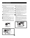
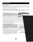
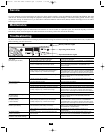
Group B DIP Switches (Select Models)
Select Load Sharing—OPTIONAL (Not on 612, 750 and 1250 Models)
Your Inverter/Charger features a high-output battery charger that can draw a significant amount of AC power from your utility source or
generator when charging at its maximum rate. If your unit is supplying its full AC power rating to its connected heavy electrical loads at the
same time as this high charging occurs, the AC input circuit breaker could trip, resulting in the complete shut off of pass-through utility power.
To reduce the chance of tripping this breaker, Inverter/Chargers may be set to automatically limit the charger output. This keeps the sum of
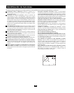
the unit’s AC load and charge power within the circuit breaker rating. This charger-limiting function has four settings, allowing you to
reduce the charger’s draw lower and lower, as needed, if the AC input circuit breaker keeps tripping under the normal AC loads of devices
you have connected downline from the unit. The figures on the next page show how to set your DIP Switches to determine how heavy the
connected load can be on your Inverter/Charger before charger-limiting begins.
A1
A2
A3
A4
B2
B1
A1A2A3A4
A1A2A3A4
A1A2A3A4
A1A2A3A4
A1A2A3A4
200407140 120V APS Owner’s Manual.qxd 9/16/2004 9:58 AM Page 6