


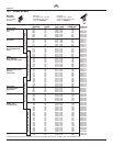
16 ProSpray3.29•3.31
GB
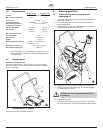
Servicing Repairs at the unit
Servicing of the unit should be carried out once annually by the
WAGNERservice.
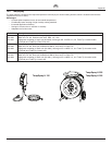
1. Check high-pressure hoses, device connecting line and
plug for damage.
2. Checktheinletvalve,outletvalveandlterforwear.
Inspect the high-pressure hose visually for any notches or
bulges,inparticularatthetransitioninthettings.Itmustbe
possible to turn the union nuts freely.
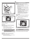
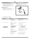
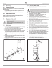
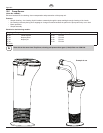
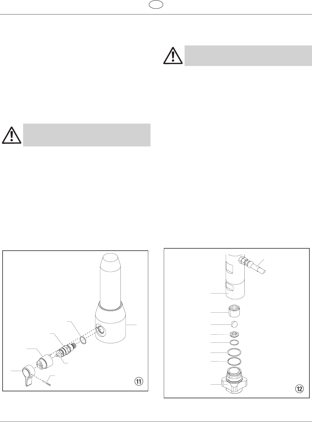
1. Useadriftpunchof2mmtoremovethegroovedpin(Fig.
11, Item 1) from the relief valve handle (2).
2. Remove the relief valve handle (2) and cam base (3).
3. Usingawrench,removethevalvehousing(4).
4. Ensure that the seal (5) is seated correctly, then screw the
newvalvehousing(4)completelyintothelterblock(6).
Tighten securely with a wrench.
5. Alignthecambase(3)withtheholeinthelterblock(6).
Lubricate the cam base with grease and slide on the cam
base.
6. Bring the hole in the valve shaft (7) and in the relief valve
handle (2) into alignment.
7. Insert the grooved pin (1) to secure the relief valve handle
in position.
5
3
7
6
4
2
1
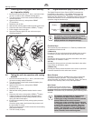
1. Remove the four screws in the front cover and then
remove the front cover.
2. Turn the pressure control knob to minimum pressure. The
DESCscreenshouldsay“PRIME”.
3. Press the #1 key on the DESC control panel. The
“CREEPMODE”screenwillnowappear.
4. Slowly turn the pressure control knob clockwise to
increase the pressure. The crankshaft/slider assembly will
begin to move very slowly.
5. When it reaches the bottom, dead-center of its stroke, turn
the pressure control knob back to minimum pressure. The
crankshaft/slider assembly should stop.
6. Unplugthepowerplugfromtheoutlet.
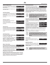
7. Pull off clamp on suction tube and remove return hose.
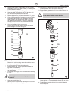
8. Unscrewtheconnectionhose(Fig.12,item1)fromthe
high-pressurelter.
9. Turn the knob on the side of the cart clockwise to unlock
the cart. Tilt the cart backwards until it locks into place.
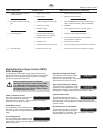
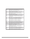
10. Loosen and unscrew inlet valve housing (2) from the lower
housing (3) with light blows from a hammer or unscrew
with an adjusting wrench.
11. Remove bearing ring (4), O-ring (5), O-ring (6), inlet valve
seat (7), inlet valve ball (8) and upper ball guide (9).
12. Clean all the parts with the corresponding cleaning agent.
Check the inlet valve housing (2), inlet valve seat (7)
and inlet valve ball (8) for wear and replace the parts if
necessary. If the worn inlet valve seat (7) is unused on
one side, install it the other way around.
13. Carry out installation in the reverse order.
Lubricate O-ring (5) with machine grease and ensure
proper seating in the inlet valve housing (2).
1
3
9
7
8
6
5
4
2