


12
breaker in the branch circuit.
2. Move the upper blade guide assembly to the
very top of its travel.
3. Make sure the blade is straight, and fully
tensioned. (A damaged or worn blade may
provide a poor reference surface for squaring
the table.)
4. Loosen the table lock knobs and hold the
table firmly against its positive leveling stop.
6. Using a machinist’s square, check to make
sure the table is 90 degrees to the blade.
USING LEATHER PROTECTIVE GLOVES,
turn the upper drive wheel to check the
squareness at a minimum of three points on
the blade
7. If the table is not level, unlock the lock nut on
the table leveling bolt.
8. Turn the leveling bolt as required to make the
table square to the blade.
9. Lock the leveling bolt lock nut and recheck the
table level. When the table is level...
10. Lock the table lock knobs securely and
recheck for level. Adjust as necessary until
the table is level while everything is tightened
to working tightness.
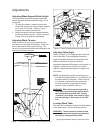
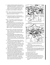
11. With everything locked down, look at the
pointer for the angle gauge. It should be
exactly on the zero mark of the gauge (Figure
12). If not, loosen the pointer screw, adjust the
pointer until it is on zero, then tighten the
pointer screw while holding the pointer se-
curely in position on zero.
Adjusting Miter Gauge Slot Parallelism
The miter slot should be parallel to the side of the
blade. If the saw is not cutting straight when using
the miter gauge, the miter slot may not be parallel.
1. Put a straight edge against the blade. Make
sure to position the blade so tooth offset does
not affect the straight edge.
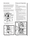
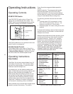
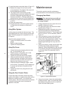
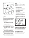
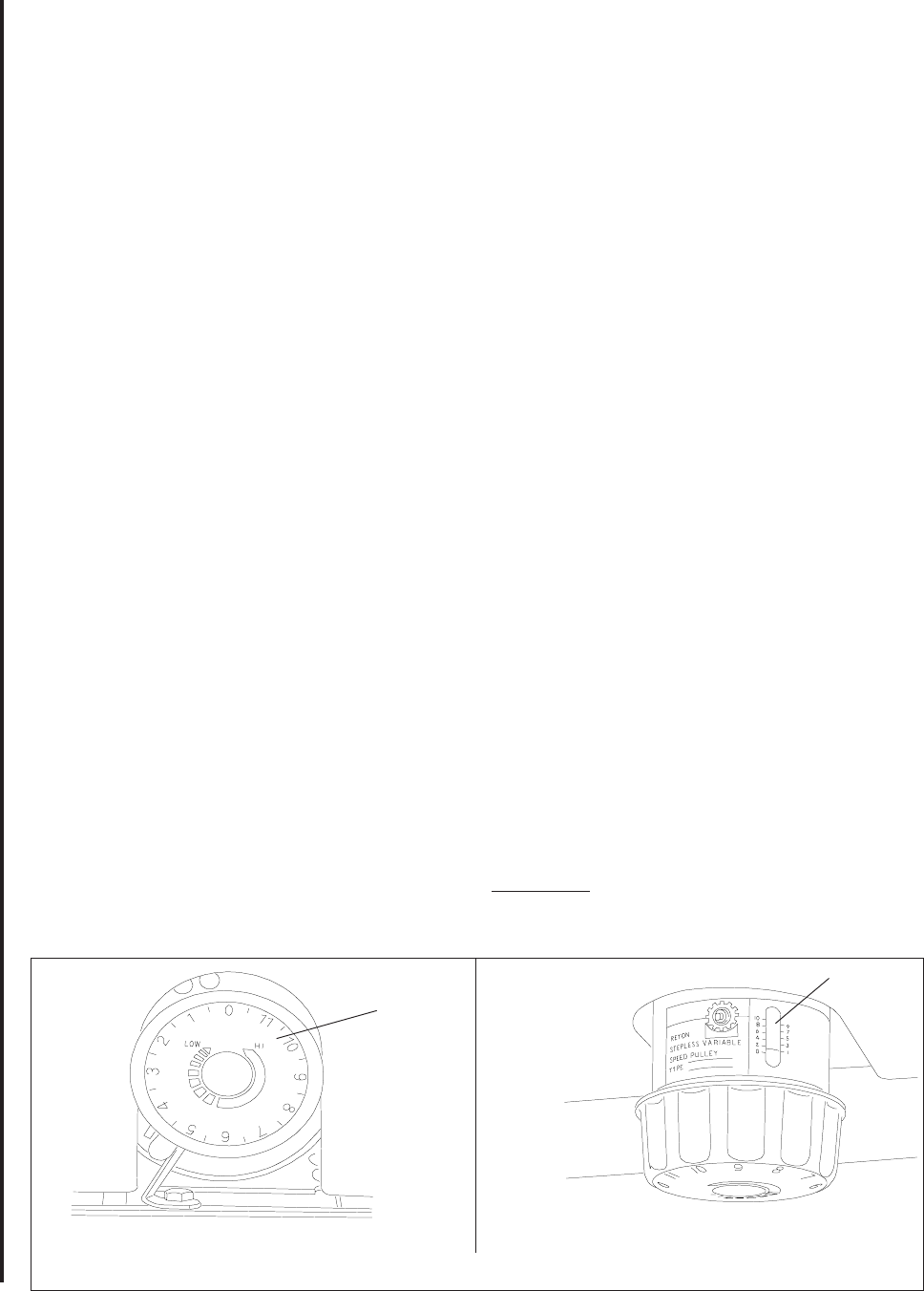
Variable
Speed
Control
Front View
Top View
Speed
Indicator
Figure 9. Variable Speed Control
2. Measure from both ends of the miter slot to the
straight edge.3. If the measurements are
not equal at both ends of the slot, loosen six
bolts securing the table to the table trunnions
(see Figures 12 and 13.)
4. Adjust the table until it is parallel with the blade.
5. Tighten the trunnion attaching bolts.
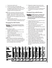
Adjusting Blade Speed
(Models 8201/8203)
Figure 6 on page 9 provides blade speeds for
various materials. To adjust the blade speed,
change the clutch position of the clutch (in or out)
and the position of the drive belt on the pulleys on
the motor and reduction gearbox shafts.
Adjusting Blade Speed
(Models 8201VS/8203VS)
See Figure 9 at bottom of this page.
1. The blade speed is controlled by an adjust-
ment mechanism on the right end of the
saw. Speed increases or decreases as the
knob is turned
2. A placard on the drive belt guard (shown
below) provides recommended speeds for
various materials.
3. A speed indicator is provided on the barrel of
the adjustment mechanism. In surface feet per
minute; Position 0 = 334, 1 = 262, 2 = 216, 3 =
171, 4 = 137, and 5 = 116.
4. Turn the speed adjustment knob to the desired
setting as determined by the material being
cut.
Changing Clutch Position
WARNING: NEVER attempt to shift the clutch
mechanism while the saw is running. The
saw must be turned off before clutch shifted.