


14
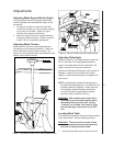
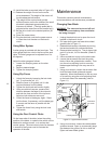
10. Install the belts as required (refer to Figure 10).
11. Release the weight of motor so the motor
pivots downward. The weight of the motor will
provide adequate belt tension.
12. The weight of the motor should provide
sufficient tension so the the middle of the small
drive belt is displaced approximately the
thickness of the belt. (The high speed belt is
adjusted at the same time as the smaller belt.)
13. Set the drive clutch to the desired position (IN
or OUT).
14. Close the access doors.
15. Plug the electrical cord into the power source
or close the circuit breaker on the branch
circuit.
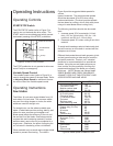
Using Miter System
A miter gauge is provided with the band saw. The
miter gauge slips into a slot in the face of the work
table. The miter gauge can be adjusted from 0 to
45 degrees.
Adjust the miter gauge as follows:
1. Loosen the clamping screw on the miter
gauge.
2. Adjust to desired angle.
3. Tighten the clamping screw.
Using Rip Fence
1. Unlock the fence by loosening the lock knob
(ref. 7) and handle (ref. 10.)
2. Slide the fence on its guides until it is the
required distance from the blade.
3. Tighten the lock knob and handle, slightly.
4. Using a machinist’s square, measure the
distance between the edge of the miter slot
and both the front and rear of the rip fence.
Adjust so both distances are equal.
5. Check the fence-to-blade gap, again. Read-
just the fence, if necessary, until the blade gap
is correct and the fence is parallel with the
miter slot.
6. Tighten the fence firmly using the lock knob
and handle.
Using the Dust Control Chute
On the lower side of the table, below the cutting
position of the blade, is a plastic tube which can be
attached to a shop vacuum, or to a shop dust
control system. The dust control chute can be seen
in several of the figures used to illustrate the
operation of the saw.
Maintenance
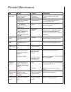
This section contains periodic maintenance
recommendations and maintenance procedures.
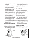
Changing Saw Blade
WARNING: The saw must be turned off and
power disconnected any time saw blades
are being changed.
1. Unplug the electrical cord or open the circuit
breaker in the branch circuit.
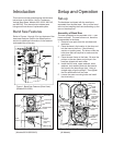
2. Pull open both upper and lower drive wheel
guards (refer to Figure 1).
3. Release blade tension completely by turning
the tension handle fully counterclockwise.
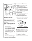
4. Remove table leveling pin. The pin has a tight
push fit in its slot; it is not threaded. (Refer to
Figure 13.
5. Use a screwdriver to pop out the table insert.
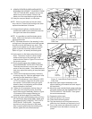
6. Loosen the set screws that lock the guide
blocks. Move the guide blocks outward. Then
turn the micro-adjusting knob to move the
blade support bearing to the very rear of its
travel.
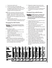
7. Using a hex wrench, loosen the set screw that
locks the lower blade guide and support
assembly. Move the assembly to the very rear
of its travel by using the micro-adjusting knob
on the back side of the assembly (refer to
Figure 11).
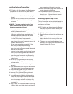
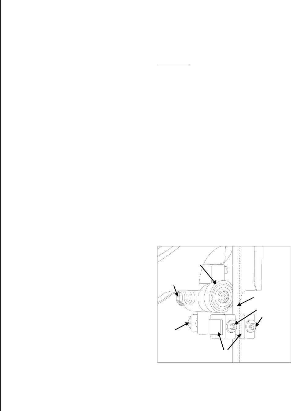
Figure 11. Upper Blade Guides
Guide block
support
microadjusting
knob
Support
bearing
microadjusting
knob
Blade support
bearing
Blade
Carbide guide blocks
Guide block
set screws
8. Using a hex wrench, loosen the carbide blade
guide set screws. Open up a reasonably large
gap between the guides; do this on both the
upper and lower blade guides.