


16
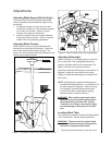
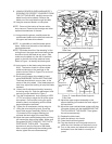
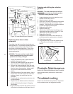
Carbide guide block
Blade
Blade support bearing
Guide block
set screws
Support
bearing
shaft
Guide block
support set
screw
Figure 14. Lower Blade Support Assembly
Replacing drive wheel rubber
protectors
The rubber rings that cover the drive wheels are
called protectors. The protectors protect the wheel
from blade damage and provide a high friction
drive force on the tensioned blade. Over a long
period of service, the protectors wear and may
require replacement.
WARNING: The saw must be turned off and
power disconnected any time the rubber
protectors are being changed.
1. Unplug the electrical cord or open the circuit
breaker in the branch circuit.
2. Remove the blade according to the step-by-
step instructions on blade replacement.
3. Remove the rubber protectors from the drive
wheels. Use a flat screwdriver blade or knife
blade to loosen the protectors, being careful
not to nick or score the aluminum drive
wheels.
4. Clean the surface of the drive wheels. Use a
solvent such as mineral spirits as required to
achieve a clean, dry surface for the new
protectors.
5. Carefully slip the replacement protectors onto
the drive wheels.
6. Replace the saw blade and return the saw to
service by following the steps in Changing
Saw Blades.
7. Plug the electrical cord into the power source or
close the circuit breaker on the branch circuit.
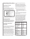
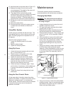
Draining and refilling the reduction
gearbox.
WARNING: The saw must be turned off and
power disconnected any time the gearbox
lubricant is being drained or filled.
1. Unplug the electrical cord or open the circuit
breaker in the branch circuit.
2. Open the door in the base.
3. Push up on the motor to loosen the drive belts.
4. Remove the pipe plug at the bottom of the
gearbox. Drain the oil into a suitable container
for safe and appropriate disposal.
5. Replace the drain plug.
6. Open the filler plug.
7. Add lubricant until the level is halfway up the
sight gauge window (refer to Figure 15). Use
Shell Spirax HD 90 gear lubricant.
8. Replace the filler plug.
9. Replace the drive belts. Allow the motor to
pivot downward to apply tension to the belts.
10. Close the access door.
11. Plug the electrical cord into the power source
or close the circuit breaker on the branch
circuit.
Oil Level Gauge
Gear Box Pulley
Figure 15. Gearbox Oil Level Gauge
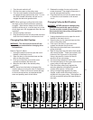
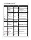
Periodic Maintenance
Refer to the Periodic Maintenance chart for mainte-
nance that should be performed at various time
intervals.
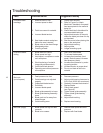
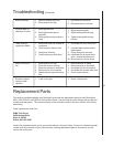
Troubleshooting
Refer to the Troubleshooting charts for equipment
fault, probable cause and suggested remedy.