


9
Installing Optional Frame Riser
NOTE: Refer to the illustrations in the Replacement
Parts section for location of the parts used on
the frame riser.
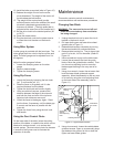
1. Remove the saw blade (refer to Changing Saw
Blades).
2. Remove the two screws at the top and bottom
of the blade guide that holds the blade guide on
the frame.
WARNING: The saw must be turned off and
power disconnected any time the rubber
protectors are being changed.
3. Unplug the electrical cord or open the circuit
breaker in the branch circuit.
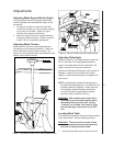
4. Support the upper frame and wheel assembly
with a strap attached to an overhead crane.
Use additional straps to be sure the frame
assembly will be held in a stable position when
it is lifted off the lower frame assembly.
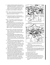
5. Remove the nut on the bolt that clamps the
upper frame to the lower frame and remove the
bolt, two washers and nut.
6. Lift the upper frame high enough off of the
lower frame to clear the riser casting.
7. Be certain the mating surfaces of the lower
frame, riser, and upper frame are all clean and
free from dirt and debris.
8. Position the riser casting over the lower frame.
Make sure the locating dowels are inserted in
the mating holes in the riser casting.
9. Lower the upper frame onto the riser casting.
Make sure the locating dowels fit into their
mating holes.
10. Put the new (longer) attaching bolt and top
washer through the upper frame and riser, into
the lower frame.
11. Put a washer and nut on the bolt and tighten
securely.
12. Attach the bracket hooks to the top and bottom
of the blade guard using self-tapping screws.
13. Attach the blade guide using the screws that
held the original (shorter) guard.
14. Remove the old (shorter) blade guide post
assembly from the upper frame.
15. The guide support assembly with the carbide
guides and blade support bearings should be
transferred to the new, longer support rod.
Several other new parts are included for this
component. (Refer to the parts illustrations for
more detail.)
16. Install a new 105-inch blade (refer to Changing
a Blade). Make sure blade tension and tracking
are checked and adjusted as required.
18. Install the extension plug cable between the
motor plug and switch plug.
19. Plug the electrical cord into the power
source or close the circuit breaker on the
branch circuit. Operate the band saw to
verify blade tracking.
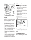
Installing Optional Rip Fence
The rip fence slides on two rails attached at the
front and rear of the work table. Install the fence
mechanism as follows:
NOTE: Refer to the illustrations in the Replace-
ment Parts section for location of the parts
used on the rip fence.
1. Slide the rails into the fence.
2. Ease the fence and rails into position on the
table.
3. Using the four spacers and four attachment
bolts, attach the rails securely to the saw
table.
4. The fence can now be adjusted and used
according the instructions in Adjustment and
Use of Optional Rip Fence.