


15
9. USING LEATHER GLOVES AND ANSI Z87.1
EYEWEAR TO PROTECT YOURSELF FROM
THE CUTTING BLADE, carefully remove the
blade from the drive wheels. Remove the
blade out of the saw table through the table.
10. Hang the removed blade in a safe place.
NOTE: Clean out the interior of the saw with a
shop vacuum. Examine the bearings and other
exposed mechanisms of the saw.
11. Using protective gloves, carefully ease the
replacement blade into the table slot and over
the upper and lower drive wheels.
NOTE: It is possible to install the blade upside
down. Make sure the teeth on the blade are
pointing downward.
NOTE: The blade should be “free standing” at the
cutting throat; the upper and lower blade guides
should not touch the blade at any point. Also,
make sure the blade is in the slot in the blade
guard on the left side of the machine frame.
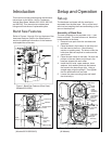
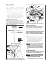
Refer to Figure 1 to identify the blade guard.
12. Apply tension to the blade using the tension
knob. The tension levels for various blade
widths are shown on the markings on the
tension device. Refer to Figure 3 for a view of
the tension system.
13. Slowly turn the upper drive wheel by hand,
while OBSERVING THE BLADE TRACKING.
The blade should track, more or less, in the
center of the drive wheel. If the blade does not
track true, adjust the tracking to keep the blade
centered.
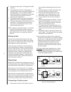
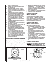
14. Unlock the tilt adjustment knob by loosening
its locking wing nut. Both the adjustment knob
and wing nut are identified in Figure 7.
15. Turn the tilt adjustment knob (usually a VERY
LITTLE at a time) to adjust the tilt of the upper
drive wheel. Do this while turning the upper
wheel by hand, and adjusting until the blade
stays centered on the wheel.
16. Tighten the tilt mechanism locking wing nut.
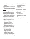
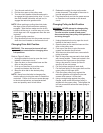
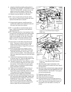
17. Using the micro-adjusting knob, move the
lower blade support assembly (Refer to Figure
12) forward until the support bearing just
contacts the back edge of the saw blade.
18. Adjust the lower carbide blade guides until they
just contact the sides of the blade. Make sure
the guides DO NOT CONTACT THE TOOTH
PORTION OF THE BLADE. The guides
should touch only the flat part of the blade.
After correctly positioning the carbide guide
blocks, tighten the set screws securely.
Blade support
bearing micro-
adjusting knob
Leveling
bolt lock
nut
Table leveling
bolt
Trunnion
attachment
bolts
Blade guide
microadjusting
knob
Front
trunnion
lock
knob
Guide
block
support
Carbide
blade guide
Blade
support
bearing
Rear
trunnion
lock
knob
Figure 12. Lower Blade Guide Support
Rear View
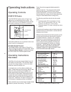
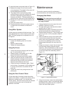
Front
trunnion
lock knob
Guide block
microadjusting
knob
Trunnion
attachment
bolt
Front trunnion
Lower blade
support bearing
Table leveling
pin
Rear trunnion
lock knob
rear
trunnion
Carbide guide block
Figure 13. Lower Blade Guide Supports
Front View
19. Adjust the upper support assembly so the
support bearing just contacts the back edge of
the saw blade.
20. Adjust the upper carbide blade guides until they
just make contact with the blade BEHIND THE
TOOTH AREA OF THE BLADE. Then tighten
the set screws securely.
21. Replace the table insert.
22. Insert the table pin into its slot.
23. Close the drive wheel guards.
24. Plug the electrical cord into power source or
close the circuit breaker on the branch circuit.
25. Turn on the power and observe the action of
the blade to sure the blade is correctly ad-
justed.