


08905154A - 17 -
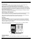
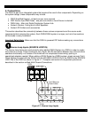
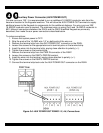
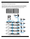
Auxiliary Power Connector (AUX POWER OUT)
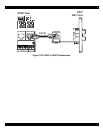
For wire runs over 150’, it is recommended to run an additional 16 AWG/2 conductor wire from the
head-end location to the Keypads locations. This will allow the AUX POWER OUT terminals to supply
additional power to the Keypads to compensate for the additional distance. For wire runs over 300’,
16 AWG/2 conductor wire is required. The maximum wire run using Cat-5 and 16 AWG/2 conductor is
600’. Make all connections between the D5XH and the D5KP Amplified Keypads as previously
described, then make the aux power connections described below.
To make connections:
1. Ensure that system power is OFF!
2. Strip the ends of the 16 AWG wire 1/4" on both ends of the wire run.
3. Remove the terminal strip from the AUX POWER OUT connector on the D5XH.
4. Loosen the screws for the appropriate zone’s terminal pairs on the terminal strip.
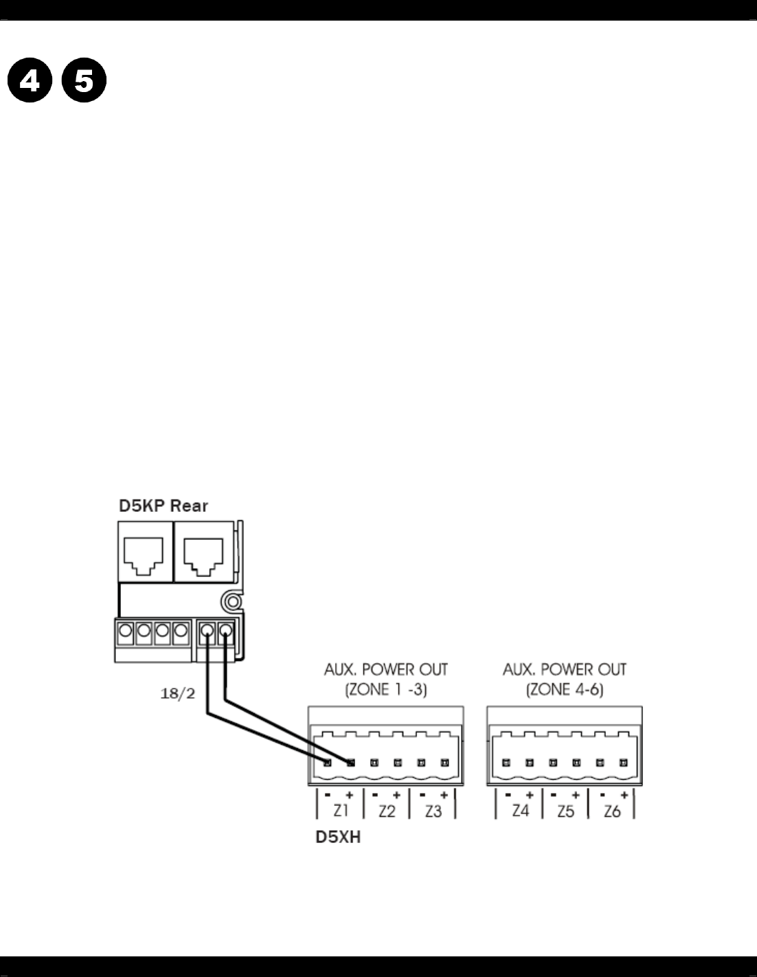
5. Insert the wires into the terminal strip, paying close attention to polarity (+/-).
6. Tighten the screws on the terminal strip.
7. Remove the terminal strip from the PWR IN connector of the D5KP.
8. Loosen the screws on the D5KP’s PWR IN terminal.
9. Insert the wires into the terminal, paying close attention to polarity (+/-).
10. Tighten the screws on the D5KP’s PWR IN terminal.
11. Connect the terminal strip back onto the AUX POWER OUT connector on the D5XH
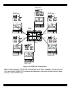
Figure 3-6: AUX POWER OUT ZONES 1-3, 4-6, Connections