


08905154A - 27 -
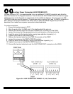
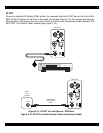
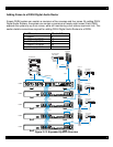
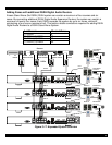
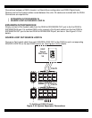
D5XH ZONE OUT
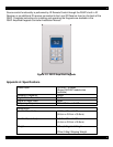
Additional zones beyond the six that connect to the D5XH are connected directly to their
corresponding D5XH’s ZONE OUT ports using Cat-5. See Figure 3-19 for details.
Figure 3-19: D5XH ZONE OUT Connections
4. Settings & Operation
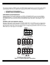
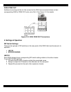
DIP Switch Settings
There are two groups of DIP switches on the rear panel of the D5XH that must be set prior to
operation:
• UNIT ID
• KEYPAD PAIRING
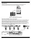
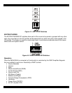
UNIT ID
Each D5XH chassis has a corresponding DIP switch setting relative to the other chassis.
To set UNIT ID DIP switches:
1. Correctly identify which chassis controls the associated zones.
2. Assign a unique unit ID based on the silkscreen on the rear panel.
3. Repeat this process for the each other expansion chassis.