


975-0697-01-01 27
Installing the Inverter/Charger
This guide for use by qualified personnel only.
Connecting the AC Output Wires
To make the AC output wiring connections:
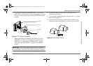
1. Remove one of the AC knockouts from the front or side of the
unit. Do not leave the knockout inside the wiring compartment.
2. Install a strain-relief clamp in the AC knockout and run the AC
wiring through the strain-relief clamp.
3. Strip approximately 50 mm off the jacket from the AC cable
and separate the wires.
4. Using a 6 mm blade slot screwdriver, loosen the terminal
screws on the AC output terminals. Do not remove the screws.
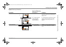
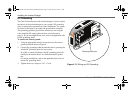
5. Connect the line and neutral wires to the output terminals
(labeled AC Output on the terminal block, Figure 6 on page 25)
as follows:
Connect Line to OUTPUT L, Neutral to OUTPUT N.
6. Tighten the terminal screws. Leave some slack wire inside the
wiring box.
7. Connect the ground wires to a free position on the ground bus,
Figure 6 on page 25. If solid ground wire is being used, the wire
can be connected directly under the screw heads. If stranded
ground wire is being used, ring terminals must also be used.
8. Secure the strain-relief clamp on the AC output cable jacket.
9. Attach the wiring compartment cover panel and tighten the four
screws.
10. Connect the outgoing AC wires to an AC load panel equipped
with circuit breakers.
EQUIPMENT DAMAGE
Do not connect the output of the inverter to any AC source.
Failure to follow these instructions can damage the unit and/or
damage other equipment.
IMPORTANT:
The applicable installation code may not allow you to run
the AC input and AC output wiring through the same AC knockout.
Freedom SW 3K2K 230V InvChg Install Guide.book Page 27 Friday, June 20, 2014 9:11 AM