


Installation
2–10 975-0251-01-01
Marine Installation
Before installing the inverter in a marine application, you must consider factors
such as:
• “Location” (see page 2–10)
• “Grounding” (see page 2–11)
• “Neutral Bonding” (see page 2–11)
• “AC Wiring” (see page 2–12)
• “Residual Current Circuit Breaker” (see page 2–13)
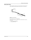
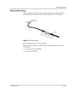
• “Remote Control Wiring” (see page 2–13)
• “DC Wiring” (see page 2–14)
• “Battery Cable Fusing” (see page 2–15).
Location
The following factors should be considered when planning to install the
Freedom 10.
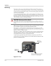
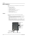
1. The chassis ground bonding lug is located on the bottom of the unit. Be
sure to make this connection before bolting the unit down.
2. Always mount the unit in a dry area, out of direct contact with water or
spray.
3. You may mount the unit horizontally (on a shelf) or vertically (on a wall or
bulkhead). If mounted vertically, you must orient the unit so the switch and
circuit breakers are facing up and the fan and battery cables are facing down.
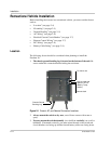
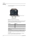
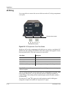
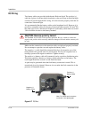
Figure 2-5
Ground, AC, and Remote Connection Locations
Remote Jack
Chassis Ground
Bonding Lug
May be used with
optional TC 2+2
(Battery Temp.
Sensor)
For future use